 English
 Chinese
info@dagyee.com
+8613961861780

Introduction
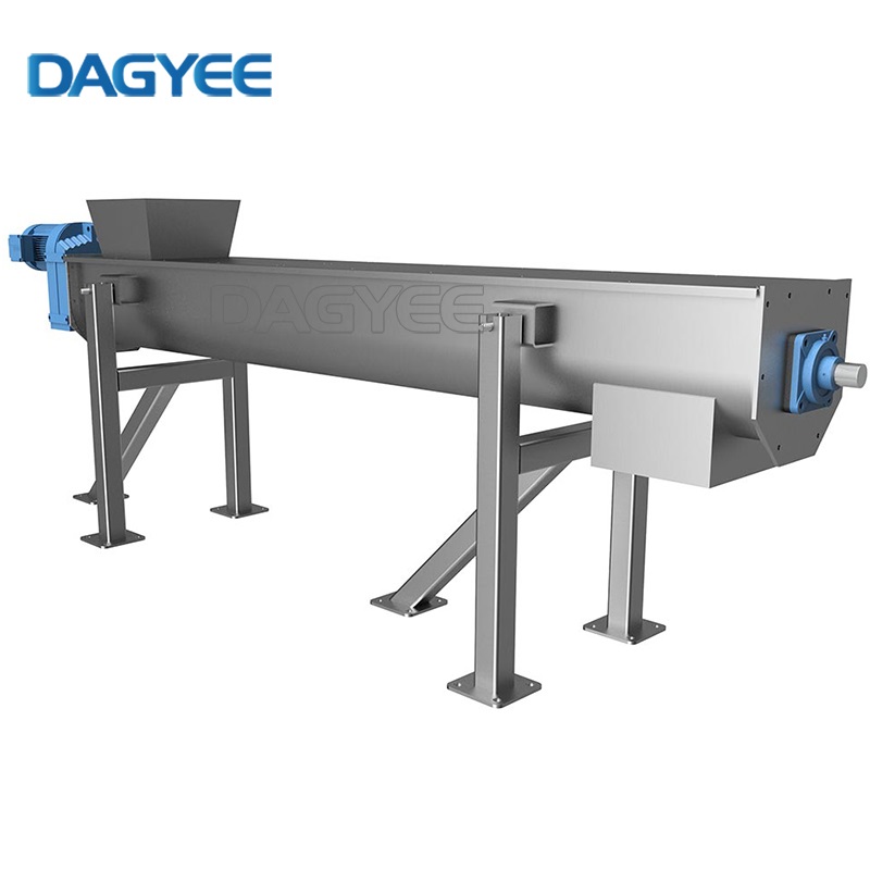
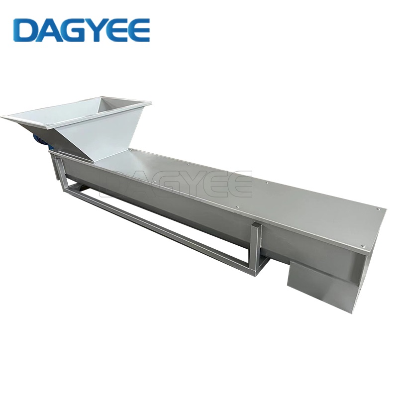
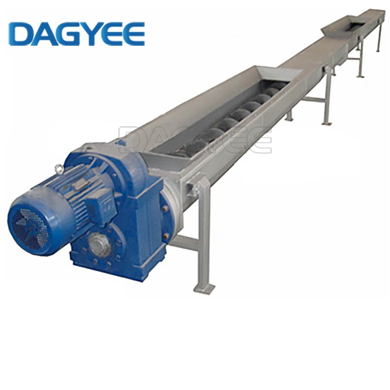
For wastewater treatment facilities, biogas generation workshops and municipal solid waste sorting stations, shaftless screw conveyors are irreplaceable bulk material transfer equipment. Compared with traditional screw conveyors fitted with central transmission shafts and hanging bearings, the shaftless spiral structure removes internal support components entirely, effectively solving frequent winding and blockage issues when transporting sticky sludge, long-fiber organic waste and kitchen residues.
Even with this obvious structural advantage, operators often overlook its unique mechanical weak points brought by the self-supporting spiral layout. Minor abnormal running signs are usually dismissed during daily shifts, which gradually evolve into sudden shutdowns, expensive component replacement work and suspended production schedules. This practical manual sorts out all observable pre-failure warning signals, analyzes real root causes collected from thousands of field operation cases, and provides step-by-step repair plans that maintenance teams can implement without advanced professional training.
We also attach three practical reference tables: standard equipment technical parameters, fault risk threshold monitoring indicators and cyclic maintenance inspection checklist. Plant managers and field mechanics can use this article as an internal operation guidance document to cut unexpected maintenance downtime by roughly 70% and prolong the service cycle of core spiral parts by two to three years.
1. Standard Technical Parameters of Shaftless Screw Conveyors (On-site Selection Reference)
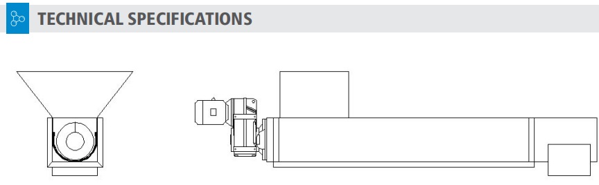
Matching conveyor specifications to actual material traits is the most fundamental way to avoid man-made mechanical failures. The data below covers mainstream models widely used in sewage, biomass and waste recycling industries; parameter adjustments are required if you handle highly abrasive sand-containing waste or high-temperature industrial residues.
| Model No. | Spiral Outer Diameter (mm) | Maximum Single Delivery Length (m) | Allowed Max Tilt Angle (°) | Normal Transport Capacity (m³/h) | Matched Motor Power (kW) | Suitable Conveying Materials |
|---|---|---|---|---|---|---|
| SCS-200 | 200 | 8 | 30 | 5–10 | 2.2 | Low-viscosity dewatered sludge, light food processing waste |
| SCS-300 | 300 | 15 | 40 | 15–30 | 4.0 | Municipal sewage sludge, palm fiber, crop straw residues |
| SCS-400 | 400 | 20 | 45 | 35–60 | 7.5 | Thickened sludge, construction mud residue, medium-volume biomass |
| SCS-500 | 500 | 25 | 45 | 65–100 | 11.0 | Large-scale biogas raw materials, industrial high-density sludge |
Key notes from field experience: Do not push the conveyor to its maximum length and maximum inclination at the same time; compound overloading will greatly accelerate spiral deformation and liner abrasion speed.
2. Real-time Fault Warning Monitoring Index Table (Daily Pre-shift Inspection Focus)
| Fault Category | Visible & Measurable Early Warning Clues | Intervention Trigger Threshold | Long-term Consequence If Unresolved |
|---|---|---|---|
| Full Material Blockage & Sudden Stall | Continuous motor current surge, raw material overflow at feed inlet, dull internal friction rumble | Operating current exceeds rated value by over 30%; material overflow visible on tank cover | Spiral root fracture, drive motor winding burnout, full production line halt |
| Spiral Edge & Tank Liner Wear | Stable feeding quantity but obvious output drop, continuous metal scraping sound, plastic liner debris mixed in discharged materials | Actual conveying capacity reduced by 20% or more; liner wear depth reaches 5mm | Direct friction between steel spiral and carbon steel tank body, tank wall perforation, material pollution |
| Reducer & Drive Motor Overheat | Hot gearbox shell, burnt insulation odor, frequent thermal protection jump stop | Reducer surface temperature over 85°C; motor casing temperature higher than 100°C | Gear tooth ablation inside reducer, permanent motor coil damage requiring complete replacement |
| Spiral Twist & Bending Deformation | Whole machine violent shaking during rotation, regular metal collision sound at discharge end, uneven gap around spiral | One-side gap between spiral and liner below 5mm; spiral axial stretching length over 20mm | Spiral repeatedly hitting discharge baffle, irreversible spiral distortion needing overall replacement |
| End Shaft Seal Liquid & Sludge Leakage | Thick sticky material seeping out from both ends of the tank, sewage mixed into bearing lubricating grease | Visible continuous leakage on seal assembly; grease emulsification detected during inspection | Bearing rust failure, ground environmental contamination, hidden slip safety risks |
3. Nine High-frequency Shaftless Conveyor Malfunctions: Root Analysis & Practical Troubleshooting Steps
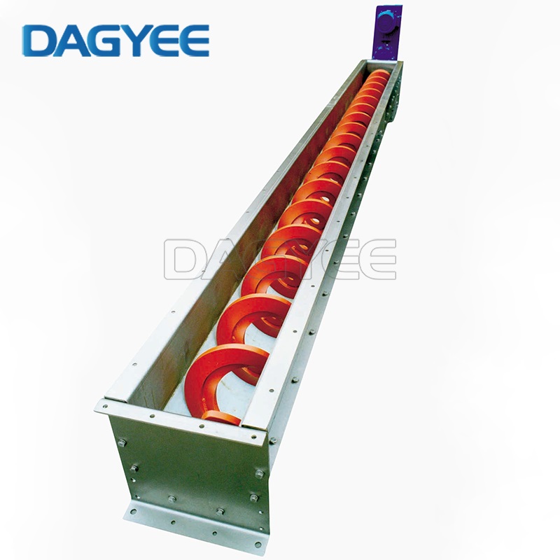
Fault 1: Internal Material Blockage and Instant Stall (Most Common On-site Failure)
Operators usually notice abnormal running status 3 to 10 minutes before complete stall. The most intuitive performance is the ammeter reading climbing sharply while feeding speed stays unchanged, plus sludge piling up and spilling out from the top of the feed hopper. If the equipment is fitted with a torque limiter, frequent alarm pop-ups will appear in this stage.
Real Root Causes Summarized From Site Cases
1.Unstable feeding rhythm: Short-time massive material input far exceeds the conveyor’s hourly design load, leading to rapid material stacking inside the U-shaped tank.
2.Poor material fluidity: High-water-content sludge and tangled fiber materials easily stick to spiral surfaces to form material arches that block the middle conveying channel.
3.Hard foreign object mixing: Stones, waste iron blocks and thick wood blocks fall into the tank through unprotected feed openings, wedging the gap between spiral and liner.
4.Improper discharge pipeline setting: Partially closed outlet gate or accumulated caked waste blocking the discharge passage.
5.Excessive installation tilt angle: When the inclination exceeds 45 degrees, part of the material slides backward under gravity and piles up in the middle section.
On-site Emergency Disposal Flow
1.Cut off the main power supply immediately, hang up lockout warning signs to prevent accidental startup during maintenance, complying with factory safety operation rules.
2.Open the detachable observation covers at the feeding section and the middle position, manually shovel out accumulated materials and take out stuck hard sundries.
3.Rotate the spiral slowly through the hand crank installed on the reducer output end to confirm no stuck resistance inside the tank.
4.Restart the equipment under empty tank conditions first, then adjust feeding equipment to a low output speed and gradually increase material supply to test stable discharging effect.
Long-term Pre-warning & Anti-blockage Optimization
Install high and low level sensors inside the feed tank to automatically pause feeding once material height hits the warning line. Add a metal grid baffle at the feeding inlet to block large hard debris. Weld short reverse spiral blades at the discharge end to reduce material backflow stacking. Strictly implement empty tank startup and emptying shutdown specifications; never cut power when the tank is full of materials. For sludge and fiber waste, control the filling ratio inside the tank below 30% at all times.
Fault 2: Spiral Edge Abrasion and Gradual Transport Capacity Decline
When transporting sand-containing sludge, mine tailings or construction waste residue, spiral outer edges will suffer continuous friction loss. Operators often ignore this issue because the machine can still run normally, until the actual processing volume drops obviously and affects the whole production efficiency.
Early Warning Manifestations
The workshop can maintain stable feeding volume, but the discharge amount per hour decreases continuously; persistent thin metal scraping noise can be heard during operation; fine liner wear powder is mixed into the finished material output. After opening the observation window for measurement, the spiral outer diameter is reduced by more than 8mm.
Triggering Factors
Long-term continuous transportation of high-abrasion raw materials; original tank liner completely worn through, resulting in direct steel-to-steel contact between spiral and tank wall; long-term full-load operation makes the spiral tightly pressed against the bottom liner during rotation. Some manufacturers use thin low-cost liners to cut equipment costs, shortening the wear cycle greatly.
Practical Repair & Preventive Schemes
For mild wear where spiral edge thickness loss is less than one-third of the original size: carry out surfacing welding of wear-resistant alloy on the outer spiral edge to recover its conveying width. If local abrasion is severe and uneven, replace the damaged spiral segment or the whole spiral assembly. Upgrade the tank internal lining to thick UHMWPE wear plates; arrange monthly inspection and replace liners once wear depth reaches 5mm. Adjust feeding flow to avoid long-term full-load running to lower friction pressure between spiral and liner.
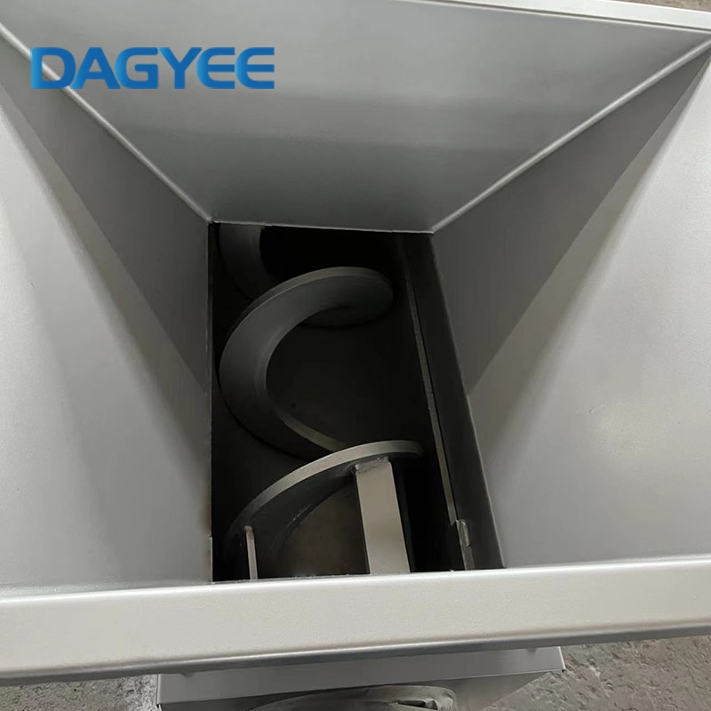
Fault 3: Spiral Bending, Torsion and Collision With Discharge End Plate
The shaftless spiral has no intermediate hanging bearing support, so it relies entirely on its own steel rigidity to bear material thrust. Once subjected to instantaneous huge torsional force, permanent bending deformation will occur easily.
Abnormal Running Signs
Whole equipment produces obvious shaking during rotation; regular loud knocking sound comes from the discharge end; the gap between spiral and liner is extremely uneven, with one side less than 5mm and the other over 25mm; measured axial stretching length of the spiral tail exceeds the safe 20mm limit.
Root Causes
Sudden blockage stall under heavy load generates strong reverse torsion to twist the spiral body; single conveying length over 12m without reserved tension adjustment structure; tail drive layout design (push-type spiral) creates larger bending stress compared with head pull drive; repeated impact from hard foreign objects hitting spiral flights.
On-site Adjustment & Repair Methods
For slight elastic deformation without permanent bending: adjust the tension nut at the spiral tail to pull the spiral back to the central position, and check the gap around the spiral to ensure uniform clearance. If the spiral has irreversible bending and torsion: use hydraulic straightening equipment for correction or directly install a new spiral. Mount travel limit switches on the discharge end baffle; the system will send an alarm and stop operation when the spiral collides with the plate. For conveyors longer than 12 meters, prioritize head drive pull structure to reduce spiral deflection range.
Fault 4: Reducer and Drive Motor Overheating, Risk of Coil Burning
Overheating of the drive system is a hidden dangerous fault. Most maintenance personnel only check temperature after obvious burnt smell appears, which often causes irreversible damage to motor windings and reducer gears.
Pre-alarm Temperature & Electrical Abnormalities
Reducer shell keeps high temperature over 85℃ for a long time (normal stable operating temperature is controlled below 75℃); motor surface temperature exceeds 100℃ with pungent burnt paint odor; thermal relay protection jumps frequently while the machine runs; gearbox lubricating oil turns black with metal abrasive powder deposited at the oil tank bottom.
Main Inducing Factors
Recurring material blockage brings continuous impact overload load to the drive system; insufficient lubricating oil inside the reducer or oil quality deteriorated due to long replacement cycles; misalignment between reducer output flange and spiral connecting plate; motor cooling fan damaged, and the equipment installed in closed narrow workshops with poor air circulation.
Complete Processing Solutions
Once the over-temperature alarm is triggered, stop operation immediately and let the drive set cool naturally for two to three hours before restart inspection. Drain deteriorated gear oil completely, clean the gearbox inner cavity and refill new lubricating oil to the standard liquid level. Re-calibrate the coaxiality between reducer and spiral coupling, tighten all connecting bolts with standard torque. Repair or replace damaged cooling fans; add ventilation air ducts for equipment installed in enclosed spaces. Configure dual protection devices including torque limiter and temperature sensor to realize automatic shutdown before the motor suffers burnout damage.
Fault 5: Tank Liner Penetration and Carbon Steel Tank Corrosion Damage
The U-shaped tank body of the conveyor is mostly carbon steel welded structure, which relies on internal wear-resistant liners to isolate friction and corrosive sewage. Once the liner fails, the tank wall will wear and corrode rapidly.
Identifiable Warning Phenomena
Small steel scraps appear in discharged finished materials; fixed-point metal scraping sound exists at a certain section of the tank body; water seepage occurs at the bottom welding seam when transporting wet sludge with corrosive components.
Main Causes of Damage
No regular monthly liner inspection and replacement plan on site; chemical sewage sludge corrodes the uncoated inner surface of the steel tank; equipment suppliers equip thin low-quality liners to reduce manufacturing costs.
Daily Warning & Maintenance Specifications
Carry out visual inspection of liner wear status through observation windows every month; replace the liner in time when wear depth reaches 5mm. For projects transporting chemical sludge and acid-base waste water, upgrade the lining to anti-corrosion modified UHMWPE plates. Brush epoxy anti-corrosion coating evenly on the inner wall of the steel tank before liner installation to slow down metal corrosion speed.
Fault 6: Whole Machine Abnormal Vibration and Loose Connecting Bolts
Long-term vibration will loosen all fasteners on the conveyor, including support stand anchor bolts, tank cover fixing screws and flange connecting bolts, further aggravating equipment operation instability.
Visible Abnormal Signals
The whole U-tank shakes violently during rotation, and the support stand has obvious displacement; regular impact vibration is transmitted to the concrete foundation ground; tank cover fixing bolts fall off after several shifts of continuous operation.
Source of the Problem
Spiral deformation leads to eccentric rotation and unbalanced friction force; the equipment support base is not leveled during installation; long-term overload impact gradually loosens all connecting fasteners.
Standard Troubleshooting Steps
Shut down the equipment completely and use a torque wrench to retighten all flange, support stand and tank cover bolts with a torque value of 40–50Nm. Fill steel gaskets under the support stand to level the base, and re-fasten the foundation anchor bolts poured into concrete. Adjust the spiral tail tension to calibrate the uniform gap around the spiral, eliminating eccentric friction vibration sources.
Fault 7: Material Arching and Sticky Layer Accumulation on Spiral Surfaces
High-viscosity dewatered sludge, fruit pulp and kitchen waste easily adhere to spiral flights. Even if the spiral keeps rotating normally, the effective conveying cross-section shrinks continuously and output drops sharply.
Early Warning Performance
Spiral rotates smoothly with no stall, but hourly discharge volume keeps falling; thick caked sticky material can be clearly seen attached to the spiral through observation windows; motor operating load fluctuates up and down irregularly.
Root Causes
Raw materials with high moisture and strong adhesion properties; equipment left idle for a long time after shutdown without cleaning residual materials; spiral operating speed lower than the design rated RPM (the recommended speed range for sludge conveyors is 10–30 RPM).
Cleaning and Preventive Optimization
Arrange high-pressure water flushing work after every shift to wash away residual sticky materials on the spiral and tank inner wall. Install fixed spray washing pipelines inside the tank for automatic periodic cleaning. Adjust the drive frequency to control spiral rotating speed within the factory recommended range. For ultra-viscous waste materials, select polished stainless steel spiral to reduce material adhesion coefficient.
Fault 8: End Shaft Seal Leakage, Sludge and Sewage Spillage
The sealing assemblies at both ends of the tank prevent internal sludge and sewage from leaking out to the drive components and ground. Aging seals are one of the easily ignored wearing parts in daily maintenance.
Abnormal Warning Clues
Sticky sludge oozes continuously from the gap between reducer shaft and tank end baffle; sludge accumulates around the end bearing seat, and the internal bearing lubricating grease is mixed with sewage to form emulsified liquid.
Failure Inducements
Rubber sealing rings crack and age after long-term operation; spiral axial reciprocating stretching repeatedly grinds the sealing ring surface; excessive internal material extrusion pressure pushes waste through tiny gaps of the seal assembly.
On-site Repair Measures
Replace worn rubber shaft seals regularly every 3 to 6 months, adjust the replacement cycle according to the corrosiveness of on-site materials. Control spiral axial stretching length within the 20mm safe limit by fine-tuning tail tension nuts. Install secondary liquid baffles outside the end seal to intercept spilled sludge and reduce bearing contamination risks.
Fault 9: Frequent False Tripping of Torque Limiter Protection Device
Many field operators will short-circuit the torque limiter to avoid frequent shutdown interruptions, which will directly lead to spiral fracture and motor burnout in the long run. It is necessary to distinguish real blockage overload from false alarm signals before handling.
Common Reasons for False Alarm Triggering
Low temperature in winter increases the initial rotation resistance of cold high-viscosity sludge; torque protection parameter value set too low during equipment debugging; dry hard material blocks the feed inlet, generating instantaneous starting overload resistance.
Optimized Alarm Setting Scheme
Adjust the torque limiter protection threshold to 1.2–1.3 times the normal stable operating torque, and never exceed 1.5 times the rated torque value. For low-temperature winter working conditions, install auxiliary heating devices on sludge storage silos or add a small amount of dilution water to reduce raw material viscosity. Clear dry caked materials stacked at the feed inlet before daily startup to cut down instantaneous startup load.
4. Cyclic Preventive Maintenance Checklist (Daily / Monthly / Quarterly Inspection Standards)
Active regular inspection and maintenance always cost far less than emergency shutdown repair work. This checklist is compiled according to the actual operation rhythm of environmental protection workshops, which can be printed and posted in the equipment operation area for mechanics to fill in inspection records.
| Inspection Cycle | Core Inspection Content | Corresponding Processing Standards When Abnormalities Found |
|---|---|---|
| Daily (5 minutes before equipment startup) | Motor operating current, reducer shell temperature; foreign sundries at feed inlet; abnormal running noise and vibration; end seal leakage status; sticky material accumulation on spiral | Record all operating data in the daily log; clear hard sundries at feed inlet; flush light material adhesion; handle seal leakage issues before startup |
| Monthly | Spiral and liner gap measurement; liner wear depth detection; spiral axial stretching length; tightness of all connecting bolts; lubricant liquid level and oil quality; functional test of all alarm sensors | Adjust spiral tail tension when stretching exceeds 20mm; replace liners with wear depth ≥5mm; refill or replace deteriorated lubricating oil; recalibrate temperature and blockage sensors |
| Quarterly | Partial disassembly to check spiral abrasion and bending deformation; unified replacement of severely worn liners and aging sealing rings; re-calibration of overload protection interlock system; full tank high-pressure flushing cleaning; support foundation stability check | Replace deformed or heavily worn spiral sections; completely clean all residual caked materials in the tank; add steel gaskets to re-level unstable support stands; archive all overhaul records |
5. Long-term Hidden Risk Elimination: Matching Design & Standardized Operation Rules
For fibrous sludge and kitchen waste conveying scenarios: adopt low-speed spiral design, full-length UHMWPE wear liner and large-aperture grid at the feed inlet. If transporting highly abrasive mineral residues, select thickened spiral flights with surfacing wear-resistant alloy and reinforced thick steel tank body. For high-inclination conveying projects, strictly control the tilt angle below 45 degrees and weld anti-backflow reverse spiral sections at the discharge end.
When purchasing new conveyor equipment, four types of pre-warning sensing devices must be configured as standard parts: reducer surface over-temperature sensor (automatic shutdown at 85℃), feed section blockage level sensor, torque overload limiter with remote alarm signal output, and discharge end spiral collision travel switch.
Formulate mandatory operation rules for all on-site operators: it is forbidden to start the machine with a full tank of materials; feeding flow cannot be arbitrarily increased beyond the equipment design parameter range; protection alarm devices cannot be removed or short-circuited at will; fixed daily cleaning cycles must be implemented for high-viscosity materials; all abnormal warning data shall be recorded in the equipment operation log for later fault traceability analysis.
Conclusion
By mastering the early warning indicators, targeted troubleshooting steps and cyclic maintenance standards covered in this article, factory maintenance teams can effectively reduce unexpected downtime and extend the service life of core spiral components by two to three years. This complete fault disposal guide is suitable for reference and use in wastewater treatment, biogas energy production, solid waste recycling and other related industries, helping enterprises improve the continuous running stability of bulk sludge conveying systems.
If you plan to purchase new shaftless spiral conveying equipment or carry out technical transformation of old production lines, you can check the technical parameter table in the first chapter to complete the matching of equipment model and on-site working conditions. For personalized fault solving schemes aiming at special high-viscosity or high-abrasion materials, you can contact professional environmental equipment engineers to obtain customized design and operation guidance.
Name: Ashely Li
Mobile:+8613961861780
Tel:+8613961861780
Whatsapp:8613961861780
Email:info@dagyee.com
Add:Room 302, Building 11-4, Hongyi Road, Xinan Town, Xinwu District, jiangsu Province, China