English
 Chinese
info@dagyee.com
+8613961861780

Introduction
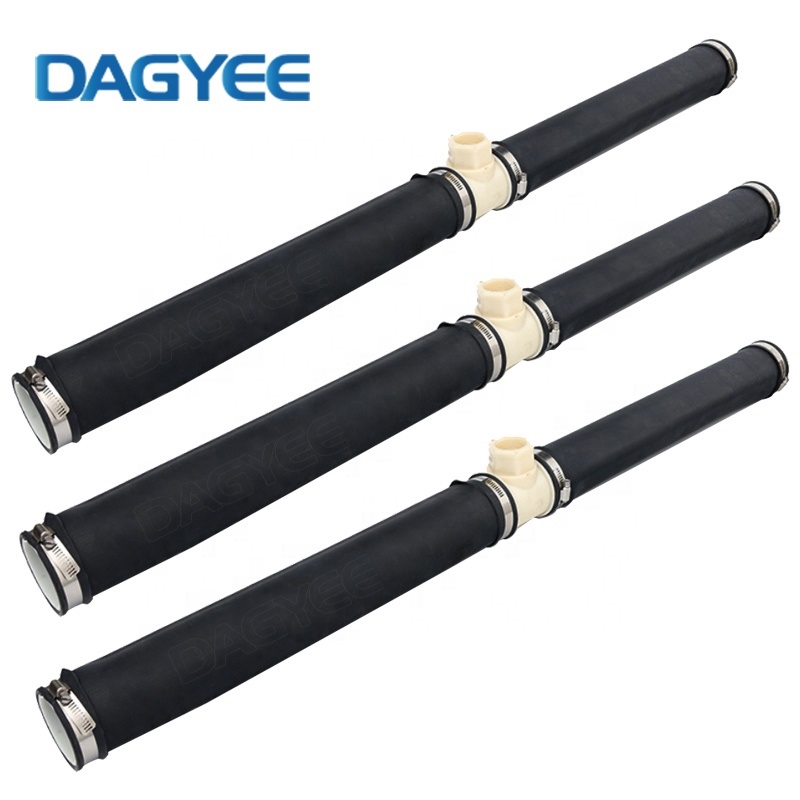
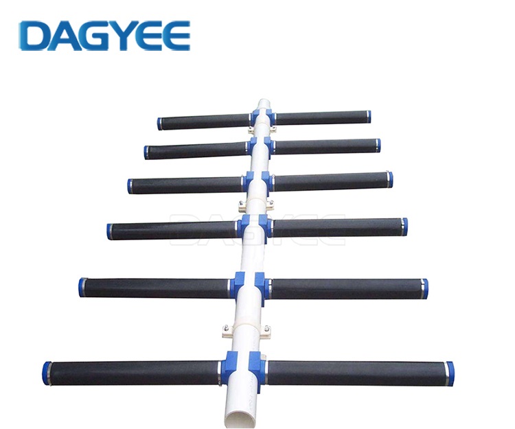
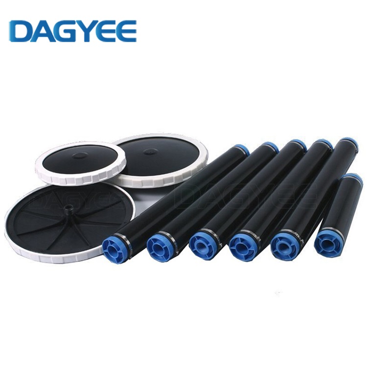
Aeration tubes, also widely known as fine-pore tube diffusers, sit at the operational heart of activated-sludge wastewater treatment facilities across municipal and industrial sectors. As one of the most popular fine-bubble aeration technologies, flexible tube-style diffusers deliver large effective bubble-generating surface area, straightforward field installation, and high adaptability for both new-build aeration tanks and retrofitting upgrade projects. Compared with disc diffuser layouts, continuous aeration tube assemblies simplify header piping arrangement in long rectangular basins, which explains their broad adoption in food processing, pulp and paper, chemical manufacturing, and domestic sewage treatment works.
Even with well-documented theoretical advantages, countless plant operators, EPC engineers and project owners encounter frustrating real-world performance shortcomings once aeration tubes go into sustained service. Too many purchasing decisions focus almost exclusively on upfront unit price, while long-term operational risks remain largely overlooked during tender and design phases. Problems tend to emerge gradually rather than appearing immediately after commissioning. Operators often notice subtle changes: higher blower running pressure, unstable dissolved-oxygen readings across different zones of the aeration basin, rising monthly electricity bills, or visible uneven bubble patterns on the tank surface. By the time obvious failure symptoms appear, substantial energy waste and hidden maintenance costs have already accumulated.
This article explores the most widespread industry pain points affecting aeration tube performance, digs into multi-factor root causes combining material science, hydraulic design, wastewater water-quality characteristics, and on-site operational habits. Real field observation data from wastewater projects are included within comparison tables, alongside practical mitigation guidance for specification, layout design, daily operation and maintenance. The goal is to support technical teams to make better-informed procurement and engineering decisions, rather than only relying on marketing claims provided by diffuser suppliers.
1. Fouling and Pore Clogging: The Dominant Source of Aeration Tube Performance Degradation
Fouling and micro-slit clogging represent the most frequently reported pain point for flexible aeration tube installations globally. After months to several years of continuous operation, the microscopic slits cut on elastomer membranes become obstructed through overlapping mechanisms: biological biofilm accumulation, inorganic mineral scaling, and physical particle deposition carried by process air and tank mixed liquor. Each fouling mode develops under different site conditions, and very few real-world sites suffer from only one single fouling mechanism in isolation.
Bio-fouling originates from naturally occurring microorganisms present in aeration tank mixed liquor. Bacteria, protozoa and extracellular polymeric substances (EPS) attach onto outer membrane surfaces and gradually infiltrate into micro-slit openings. The sticky organic matrix forms a tough layered biofilm that cannot be removed simply by temporarily increasing blower airflow rate. Even periodic high-air-flow bumping cycles can only strip loosely attached surface biomass, leaving embedded organic residues deep inside slit structures.
Inorganic scaling occurs prominently at sites receiving hard-quality feed water, where calcium, magnesium, iron and manganese ions continuously circulate within the aeration basin. Moisture carried by compressed blower air amplifies this issue: humid air condenses inside aeration tube interiors, triggering mineral salt crystallization directly along slit edges. Over extended runtime, crystalline deposits narrow or completely seal bubble outlets. For industrial wastewater facilities treating mining-influenced effluent or high-hardness process wastewater, scaling-driven clogging can progress far faster than typical municipal installations.
Physical particle bridging takes place when fine suspended solids, broken sludge flocs and miscellaneous debris lodge within micro-slit gaps. Once particles become wedged inside narrow openings, normal aeration pressure cannot dislodge them. Over time, stacked solid particles create permanent blockages across sections of the tube length.
Clogging triggers cascading negative operational consequences throughout the whole aeration system. Dynamic Wet Pressure (DWP), the core on-site monitoring indicator for diffuser condition, creeps upward steadily. Blower units must generate higher discharge pressure to maintain design air flow rate, pushing up overall aeration energy draw. Field data collected from municipal wastewater plants shows energy consumption increases ranging from 15 % to 28 % for heavily fouled aeration tube systems.
Standard Oxygen Transfer Efficiency (SOTE) drops alongside rising DWP. Even when blowers deliver greater total air volume, dissolved-oxygen set-points cannot be reliably maintained. Many municipal facilities record annual SOTE decay rates of 3-4 % under normal operating conditions; heavy-duty industrial sites can observe efficiency losses exceeding 6 % each operating year. Partial, non-uniform clogging creates patchy bubble distribution: some sections release large coarse bubbles while neighbouring zones show minimal bubble output. This creates low-DO dead zones inside aeration basins, harms biological treatment performance, destabilizes activated-sludge settling properties, and raises risks of effluent quality non-compliance.
Traditional countermeasures include offline chemical soaking, online recirculated chemical cleaning and high-pressure water jet washing. Each cleaning method brings its own trade-offs. Offline chemical cleaning requires tank draining, forcing partial or full-plant shutdown and lost treatment capacity. Online chemical cleaning avoids full drainage yet consumes considerable volumes of acid or oxidant chemicals, adding recurring operational expenditure. Repeated mechanical jet washing inflicts physical stress on elastic membrane slits. Most critically, heavily aged and irreversibly fouled aeration tubes cannot recover original factory-level SOTE performance no matter how thoroughly cleaning procedures are executed.
Table 1: Aeration Tube Fouling Mechanisms, Trigger Conditions & On-Site Symptoms
| Fouling Mode | Typical Trigger Site Conditions | Key Observable Symptoms |
|---|---|---|
| Biological Bio-Fouling | Municipal sewage, moderate organic loading, low-frequency air bumping operation, long steady running cycles | Patchy biofilm coating on tube surface, gradual DWP rise, uneven bubble distribution |
| Inorganic Scaling | High-hardness influent, iron/manganese-rich wastewater, un-dried compressed process air | Hard crystalline deposits on slit openings, sharp DWP increase, local zero-bubble segments |
| Solid Particle Bridging | High suspended solids inlet, broken sludge flocs, debris entering aeration basin | Random scattered blocked segments, localized coarse bubble blow-out at damaged slits |
| Mixed Combined Fouling | Most real-world municipal & industrial wastewater sites | Continuous multi-year DWP drift, progressive SOTE loss, partial aeration dead zones |
2. Membrane Aging, Tearing and Premature Mechanical Failure
Modern aeration tubes rely on elastic elastomer membranes, most commonly EPDM or silicone formulations, with precision-cut micro-slits that open under air pressure and close when blower output stops. This flexible mechanical design delivers excellent fine-bubble generation, yet remains vulnerable to multiple degradation pathways under harsh submerged wastewater conditions. Premature membrane damage represents another costly industry pain point, frequently driven by chemical attack, cyclic pressure fatigue, and physical abrasion.
Chemical corrosion poses major risks for industrial wastewater installations. Hydrogen sulphide, oily substances, polar solvents, and fluctuating pH values all degrade generic-grade elastomer materials. Low-formulation EPDM material will experience swelling, surface hardening, or progressive brittleness upon sustained exposure to sulphide-rich streams. Once membrane elasticity degrades, micro-slits lose their ability to seal tightly during blower shutdown cycles. Wastewater mixed liquor back-penetrates into the interior cavity of aeration tubes, bringing sludge and mineral particles inside the tube body and accelerating internal clogging.
Cyclic pressure fatigue accumulates over thousands of blower start-stop cycles. Each operational cycle stretches membrane slits open under air pressure; when airflow ceases, elastic material contracts again. Repeated stretching-relaxation cycles cause permanent slit deformation over time. Widened slits produce oversized coarse bubbles, cutting fine-bubble oxygen transfer performance substantially. Water-hammer shocks generated during system startup amplify this fatigue damage, particularly for installations without proper pressure-relief piping design.
Physical puncture and surface abrasion occur from turbulent flow, sharp solid particles carried in mixed liquor, floating tank debris, or careless underwater maintenance operations. Local tearing on one tube segment creates concentrated air blow-out points. Large volumes of compressed air escape through damaged locations, robbing downstream tube sections of required airflow and generating severe aeration imbalance across the basin.
A widespread misconception within the wastewater sector assumes all aeration tubes deliver comparable service life. In practical engineering reality, product lifespan varies enormously according to raw-material formulation, manufacturing quality, and actual water-quality environment. Economy-grade aeration tubes may develop obvious cracking and tearing within 12-24 months under heavy industrial wastewater loading. High-quality specially compounded EPDM aeration tubes can achieve 5-8 years stable runtime in well-managed municipal conditions. Unexpected early-stage replacement creates substantial capital expenditure, together with unplanned shutdown losses associated with tank draining, tube removal and reinstallation work.
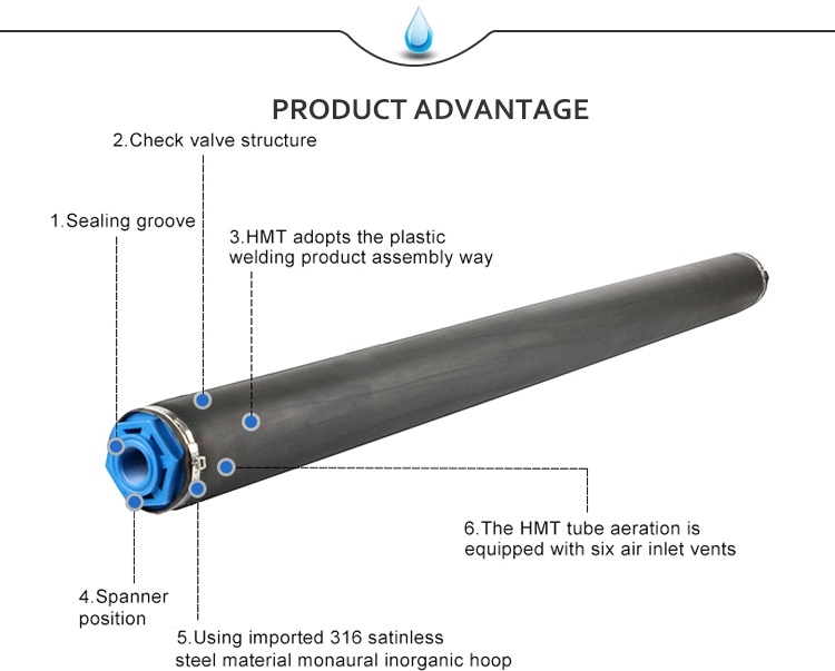
Table 2: Typical Technical Parameters of Commercial Fine-Pore Aeration Tubes
| Parameter | Standard EPDM Aeration Tube | High-Grade Anti-Fouling EPDM Aeration Tube | Reinforced Silicone Aeration Tube |
|---|---|---|---|
| Common working temperature range | 5-40 °C | 5-45 °C | -10-60 °C |
| Nominal wall thickness | 2.0 mm | 2.5 mm | 2.3 mm |
| Slit type | Laser cut micro-slit | Optimized laser micro-slit | Precision mechanical cut slit |
| Suggested single tube maximum length | 1000 mm | 1200 mm | 1000 mm |
| Recommended air flow per meter | 3-8 m³/(h·m) | 3-9 m³/(h·m) | 2-7 m³/(h·m) |
| Initial SOTE (under standard test conditions) | 28-32 % | 32-37 % | 30-35 % |
| Estimated service life (municipal sewage) | 3-5 years | 5-8 years | 4-7 years |
| Suitable wastewater scenario | General municipal sewage | Municipal, moderate-strength industrial | Oily, partial chemical industrial wastewater |
| Main weakness | Fast fouling under harsh industrial water | Higher unit procurement cost | Poor anti-fatigue under frequent pressure cycling |
3. Uneven Air Distribution Caused by Tube-Length-Induced Pressure Drop
Long continuous aeration tube layout brings well-known engineering trade-offs. As compressed air travels from the air-header inlet toward the far terminal end of each aeration tube, frictional resistance generates progressive pressure loss across tube length. Different positions on the same aeration tube experience different internal working pressure, resulting in inconsistent slit opening magnitude and uneven bubble output. This pain point frequently goes unaddressed during design phase because many EPC teams only calculate total system air volume while ignoring distributed pressure simulation along each diffuser tube.
In real tank operation, sections near the air header receive higher internal pressure: slits open wider, generating excessive air volume and relatively large bubbles. Tube sections close to the distal terminal end suffer pressure attenuation, leading to insufficient airflow output, weak bubble release or even partial zero-aeration segments. Even when total blower output satisfies theoretical design calculation, local low-dissolved-oxygen zones emerge inside the aeration basin. Insufficient local DO inhibits organic pollutant biodegradation, encourages sludge settling, and deteriorates overall treatment stability.
This challenge becomes especially prominent for tank retrofitting projects. Existing basin dimensions constrain header pipe layout options. Project teams sometimes install overly long individual aeration tubes to simplify on-site piping work, without multi-point air supply balancing design. Once installation completes, aeration non-uniformity becomes a built-in system defect that cannot be corrected through blower parameter tuning alone. Many operators attempt to compensate by raising total blower airflow, which only amplifies energy waste without fundamentally solving zone-to-zone aeration imbalance.
Proper engineering practice sets firm limits for maximum single aeration tube length according to inner diameter, material and design airflow rate. For longer basin zones, segmented tube layout with multiple air feed points helps offset frictional pressure drop and homogenize aeration performance. Unfortunately, many low-cost bidding projects sacrifice this detail to cut material and installation hours, transferring performance risks to end-user plant operators.

4. Hidden Full-Lifecycle Cost Trap Beyond Upfront Purchase Price
Procurement teams frequently evaluate aeration tube products purely based on unit purchase price. This narrow assessment overlooks large hidden long-term costs, creating one of the most costly industry-wide pain points. Low-priced aeration tube options appear economically attractive at tender stage, yet generate cumulative heavy operational burdens year-over-year.
Aeration accounts for 45 %-75 % of total power consumption for typical activated-sludge wastewater plants. Even moderate aeration-tube performance degradation translates into considerable incremental electricity expenditure. Cheap diffuser products suffer faster fouling and ageing, pushing blower operating pressure upward continuously. Over multiple operating years, extra energy bills can greatly exceed the initial cost difference between economy-grade and high-specification aeration tubes.
Maintenance-related costs constitute another major hidden burden. Short-lifespan aeration tubes demand regular underwater inspection, disassembly and replacement. Most aeration tube assemblies sit at the tank bottom; major maintenance often requires basin draining, triggering partial or complete facility shutdown. Production interruption losses for industrial wastewater sites can dwarf spare-part material costs.
Compliance risk adds further indirect cost. Degraded aeration tubes create unstable dissolved-oxygen conditions, which may cause effluent parameters to breach regulatory discharge limits. Fines, mandatory process adjustment and reputational damage for plant operators represent non-monetary yet highly impactful consequences.
High-specification aeration tubes carry higher upfront procurement expense, yet maintain stable SOTE performance across longer runtime, lower cleaning frequency and reduce average blower working load. The core industry dilemma lies in the lack of practical unified field evaluation standards. Suppliers provide laboratory-generated datasheet figures, but purchasers cannot easily verify real-world anti-fouling and anti-ageing performance before actual installation. Table 3 contrasts cost-driving factors between low-cost and high-grade aeration tube solutions across the full asset lifecycle.
Table 3: Full-Lifecycle Cost Comparison for Different-Grade Aeration Tube Solutions
| Cost Item | Low-Cost Economy-Grade Aeration Tube | High-Grade Specified Aeration Tube |
|---|---|---|
| Initial procurement unit cost | Low | Moderate-High |
| Blower energy consumption trend | Fast rising after 1-2 years | Slow, stable growth over years |
| Expected cleaning frequency | Frequent (2-3 times every year) | Low (0-1 times every year) |
| Typical service runtime before large-scale replacement | 2-4 years | 5-8 years (municipal application) |
| Tank draining & shutdown frequency for maintenance | High | Low |
| Cumulative total 6-year full-lifecycle cost | High (energy + maintenance heavy) | Moderate (higher CAPEX, much lower OPEX) |
| Effluent compliance risk level | Elevated | Relatively low |
5. Material-Mismatch Risk from Incorrect Product Specification
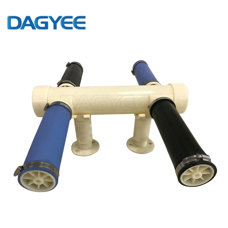
EPDM and silicone are the two dominant membrane material choices for modern aeration tubes, and material-working-condition mismatch remains extremely common across wastewater projects. Many specification decisions rely on supplier suggestions or historical project habits instead of matching material properties against actual wastewater quality data.
Standard-formula EPDM delivers excellent elasticity and fatigue resistance for conventional municipal sewage. However, ordinary EPDM performs poorly when continuously exposed to oily wastewater, high-sulphide effluent or certain solvent-containing industrial streams. Under these harsh water-quality conditions, generic EPDM membranes swell, harden or crack within short operating cycles.
Silicone aeration membranes feature good chemical tolerance toward selected oily and high-temperature waste streams. On the downside, silicone shows inferior anti-fatigue capability under frequent blower start-stop and cyclic pressure variation. Repeated mechanical stretching accelerates permanent slit widening, causing early loss of fine-bubble performance.
Every material has its own application boundaries. There exists no universal aeration-tube membrane suitable for all types of wastewater. Engineering mistakes frequently occur when project teams select material purely according to price or past municipal-project experience without analysing influent water-quality profiles. Material incompatibility triggers accelerated fouling, swelling or unexpected rupture, even when installation and blower system follow standard design requirements.
6. Practical Mitigation Strategies to Address Core Aeration-Tube Pain Points
First, match membrane material formulation against real-site water-quality parameters. For high-sulphide, oily industrial wastewater streams, select specially compounded anti-ageing EPDM or reinforced-grade silicone aeration tubes, rather than generic commodity-grade products. Request suppliers to provide reference case records under comparable wastewater conditions instead of only reviewing laboratory test reports.
Second, optimize aeration tube layout and control single-tube maximum allowable length. Respect frictional pressure-drop limits during design phase. For long aeration zones, adopt multi-point air feeding layout to balance internal pressure across tube assemblies. Avoid excessively long individual tubes for retrofitting projects even when it simplifies header piping work.
Third, tune operational regimes to slow fouling progression. Implement periodic airflow bumping cycles following supplier-recommended procedures. Keep blower operating range within the advised airflow window for installed aeration tubes. Avoid sustained ultra-low airflow or long-term over-loading conditions, both of which speed up membrane degradation and fouling accumulation.
Fourth, establish routine Dynamic Wet Pressure (DWP) trend monitoring. Track DWP change over months and years as a key indicator for diffuser condition. Schedule proactive maintenance according to pressure-drift trends, instead of waiting for obvious aeration failure and emergency repair scenarios. Historical DWP records also provide valuable data reference for future equipment upgrade and budget planning.
Fifth, perform full-lifecycle cost assessment during tender and procurement work. Compare expected service runtime, anti-fouling characteristics and long-term energy-saving potential, rather than making purchasing decisions based only on per-unit material price. Request suppliers to provide long-term reference project contact possibilities for cross-verification of real-world performance.
7. Frequently Asked Questions (FAQ)
Q1: Is it technically possible for aeration tubes to achieve zero fouling during real wastewater operation?
No commercially available fine-pore aeration tube can achieve complete fouling resistance under actual wastewater operating conditions. Bio-substances, mineral ions and suspended solids always exist inside mixed liquor. The practical engineering objective is not total fouling elimination, but slowing fouling progression, extending stable operational cycles and reducing maintenance frequency via correct material selection, layout design and proper daily operation.
Q2: What service-life expectation should plant operators hold for aeration tubes?
Under well-managed municipal wastewater conditions, qualified high-grade EPDM aeration tubes can deliver stable performance for 5-8 years. For harsh industrial wastewater environments, service life strongly depends on influent water quality and membrane material grade. Generic economy-grade aeration tubes in tough industrial conditions may only achieve 2-4 years usable runtime. Site-specific conditions always override datasheet nominal figures.
Q3: Can regular chemical cleaning permanently solve aeration-tube clogging problems?
Chemical cleaning can partially restore aeration-tube performance, yet it cannot act as a permanent fix. Repeated chemical exposure accelerates elastomer membrane fatigue. Cleaning works as a corrective maintenance measure. Preventive specification and operational tuning deliver far better long-term outcomes than relying entirely on post-clogging cleaning work.
Q4: Why does aeration imbalance still occur even if total blower air volume matches design calculation?
Total air volume only represents aggregate flow rate. Uneven pressure drop over aeration tube length, partial clogging and header-piping hydraulic imbalance will create local airflow deviation. Total-volume compliance cannot guarantee uniform bubble distribution across every section inside aeration basins.
8. Final Conclusion
Industry-wide aeration-tube pain points stem from overlapping material limitations, hydraulic design defects, complex real-world wastewater chemistry, and short-sighted procurement decisions. A large share of premature diffuser degradation and performance loss is predictable and avoidable at project design and procurement stages. For both new-build and retrofitted municipal and industrial wastewater facilities, aeration-tube specification should balance upfront capital investment, anti-fouling capability, mechanical durability and whole-lifecycle energy expenditure. Plant operators and EPC teams benefit greatly from combining supplier-provided datasheet data with practical reference from similar field projects.
When evaluating aeration-tube solutions, focus less on marketing descriptions and more on material formulation boundaries, layout pressure-drop constraints and long-term operational-cost forecasting. If you are working on new-build or aeration-tank retrofitting projects, technical review based on your actual influent water-quality data and basin geometry helps filter unsuitable options early in the project cycle.
If you need technical support for aeration-tube specification and layout suggestion for your wastewater project, feel welcome to share your water-quality parameters and tank dimension information for our engineering team’s reference.
Name: Ashely Li
Mobile:+8613961861780
Tel:+8613961861780
Whatsapp:8613961861780
Email:info@dagyee.com
Add:Room 302, Building 11-4, Hongyi Road, Xinan Town, Xinwu District, jiangsu Province, China