English
 Chinese
info@dagyee.com
+8613961861780

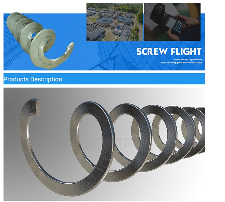
As the fundamental load-carrying element inside screw conveyors, shaftless augers, sludge transport systems and solid waste processing equipment, screw flights (often referenced as auger flighting) define the overall reliability of bulk material handling systems. For decades, helical flight structures have remained a cost-effective conveying solution for industries ranging from municipal wastewater treatment and mineral extraction to biomass power generation, food processing and chemical manufacturing. Even with mature application history, the entire screw flight supply chain continues to struggle with persistent technical and commercial challenges. These long-standing pain points stem from inherent forming process restrictions, harsh onsite operating environments, inconsistent fabrication standards and information gaps between equipment purchasers and component manufacturers. Unaddressed flight defects trigger accelerated wear, unexpected structural fractures, falling conveying efficiency and costly unplanned production shutdowns.
Many plant managers and mechanical procurement teams only recognise screw flight-related problems once severe failures occur. Early-stage geometry deviation, hidden welding stress and gradual edge abrasion rarely attract attention during routine maintenance. In this guide, we break down industry-wide screw flight challenges across manufacturing, field operation and global supply chains. We compare the strengths and natural limitations of the two dominant flight production technologies, analyse typical failure modes, provide practical material selection guidance and summarise proven engineering solutions to minimise premature flight replacement.
1. Core Manufacturing Pain Points Affecting Screw Flight Precision & Consistency
The final performance of any screw flight begins on the production floor. Fabricators of all sizes, from small regional workshops to large industrial component factories, face shared technical hurdles that are difficult to eliminate through simple process adjustments. Most difficulties originate from the mechanical behaviour of metal plates during cold forming, alongside limitations in assembly and welding workflows.
1.1 Springback Errors During Cold Forming
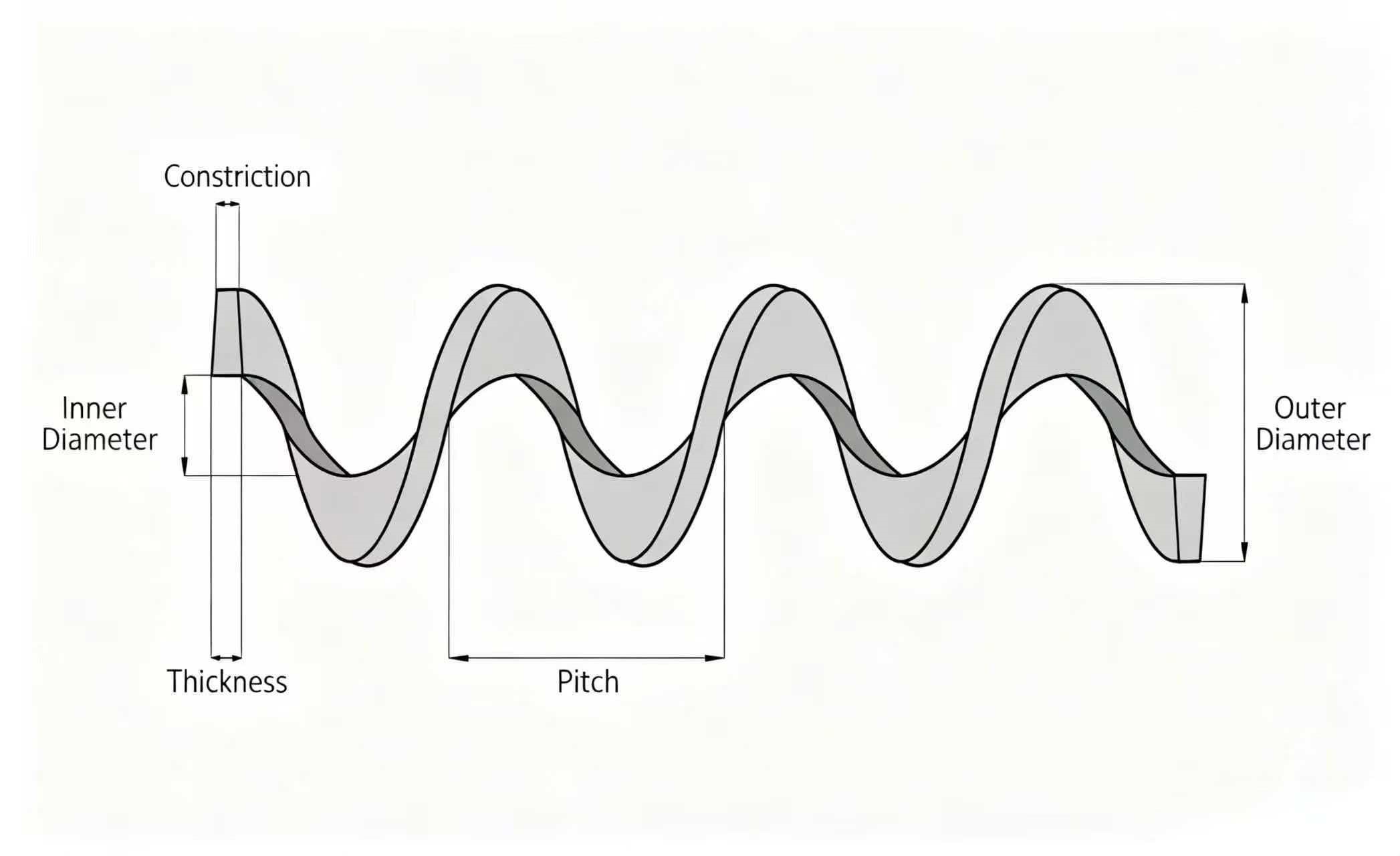
Cold forming remains the most widely adopted production method for standard and custom screw flight orders. Flat steel strips or segmented plates are pressed, bent or continuously rolled into helical profiles under room temperature. Once external forming pressure is released, internal residual stress inside the metal triggers springback. This physical effect alters critical dimensional parameters including helical pitch, outer diameter, inner hub diameter and helix curvature.
Without CNC closed-loop forming equipment and pre-calculated springback compensation data, operators must rely on repeated trial bending to hit required tolerances. Each failed trial creates steel scrap, raises raw material consumption and extends lead times. The challenge becomes far more prominent when working with high-tensile wear-resistant steel, duplex stainless steel and nickel-based alloys. Higher alloy content improves corrosion and abrasion resistance yet amplifies springback instability, making precision shaping significantly harder compared to ordinary carbon steel or AISI 304 stainless steel.
1.2 Natural Drawbacks Separating Helicoid Flight and Sectional Segmented Flight
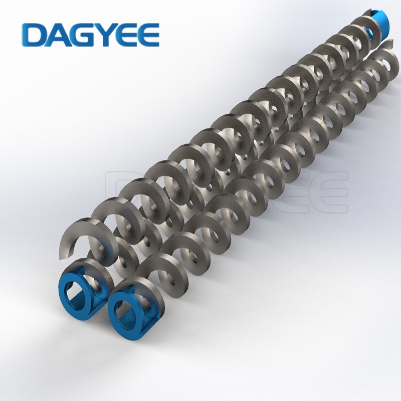
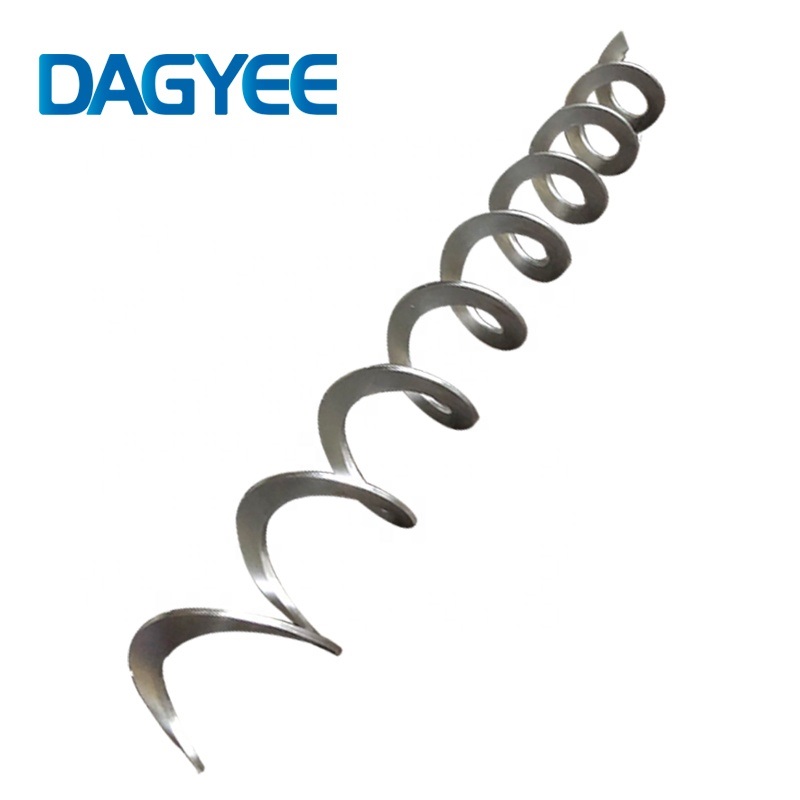
Global screw flight production splits into two mature technical routes: continuous helicoid flighting and sectional segmented flighting. Neither manufacturing method delivers universal advantages, and each carries unavoidable built-in weaknesses. Incorrect technology selection based solely on upfront price is one of the most frequent mistakes industrial buyers make.
Table 1: Helicoid Continuous Flight vs Sectional Segmented Flight Technical Comparison
| Comparison Item | Helicoid Continuous Flight | Sectional Segmented Flight |
|---|---|---|
| Production Principle | Single steel strip continuously rolled into one-piece helix | Independent arc segments pressed separately then welded sequentially |
| Plate Thickness Uniformity | Outer flight edge becomes thinner after rolling compression | Consistent thickness from inner root to outer tip |
| Maximum Available Size Range | Restricted in large diameter, extra thick plate and variable pitch applications | Supports large diameter, heavy plate, variable pitch and shaftless screw requirements |
| Weld Joint Quantity | Zero welded joints on flight body | Multiple segment weld seams along helix length |
| Stress Distribution | Continuous uniform stress distribution; no localised weld stress | High residual stress concentrated on every welding joint |
| Typical Service Limitation | Rapid edge abrasion under heavy abrasive materials | Weld crack risk under cyclic torsion and vibration |
| Lead Time for Standard Orders | Shorter for fixed-size mass orders | Longer due to multi-step forming and welding processes |
| Representative Application | Light-duty conveying, fine powder, low-abrasion materials | Heavy-duty sludge transport, mineral sand, high-wear bulk solids, shaftless augers |
Continuous helicoid flight delivers smooth material flow thanks to its seamless helical surface. Still, the rolling process squeezes material towards the flight’s outer circumference, thinning edge material permanently. In abrasive environments, thinning edges wear through quickly, widening clearance between flight tips and conveyor casings. Rising clearance causes material backflow and directly lowers system throughput.
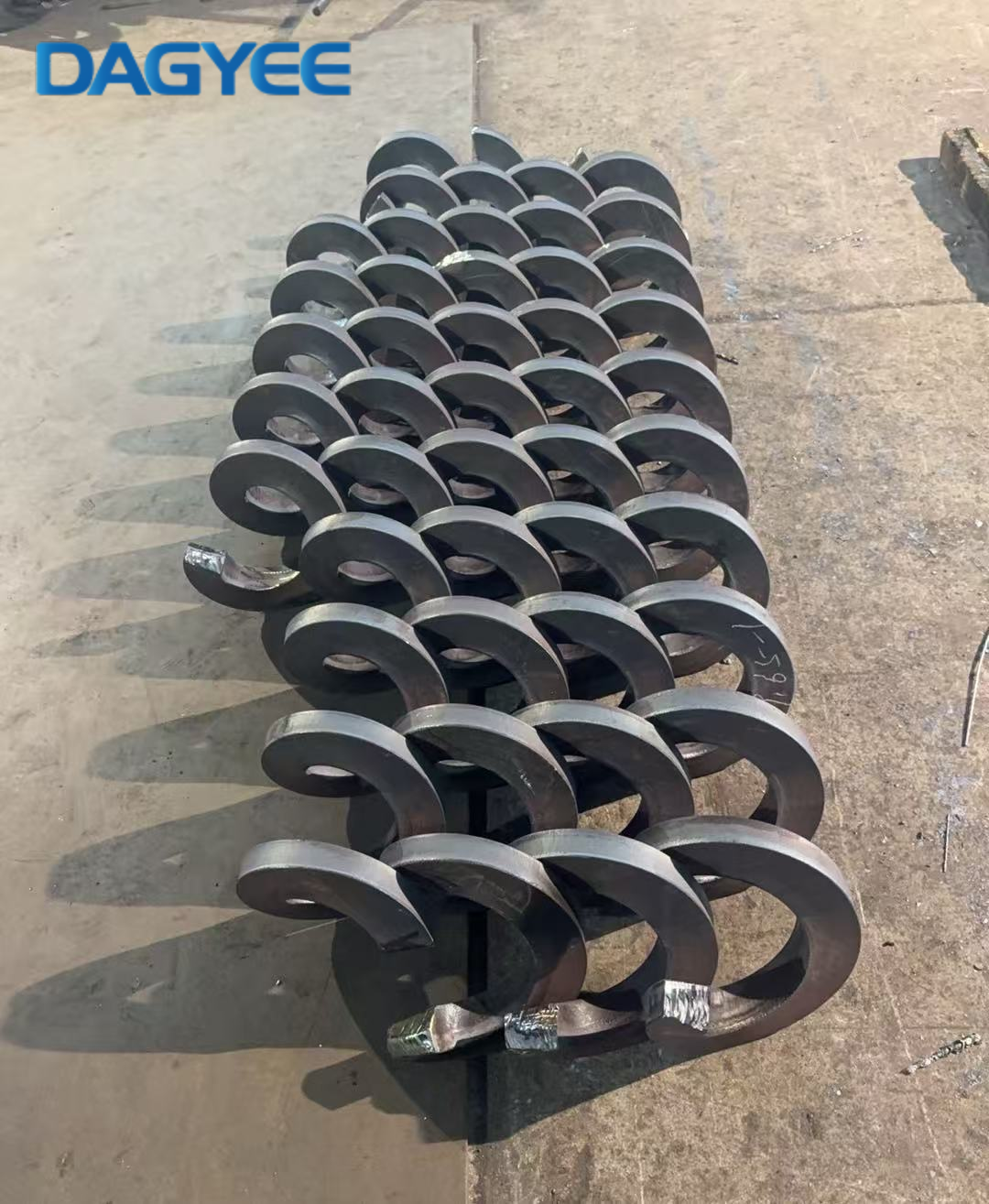
Segmented flight avoids uneven thickness, yet the dense network of welding seams creates natural weak points. When auger systems run under fluctuating loads, alternating torsion force propagates tiny cracks starting from weld boundaries. Over weeks or months of continuous operation, crack expansion may cause complete flight fracture. For long-length screw conveyors and shaftless screw systems, assembly welding also introduces helix distortion risks, leading to persistent casing scraping during rotation.
1.3 Welding Deformation Challenges & Limited Digital Pre-Simulation
For large-diameter flights, long auger assemblies and all shaftless screw flight products, multi-stage assembly welding creates uneven thermal stress. After cooling, overall helix geometry deviates from original design drawings. If circularity and concentricity drift beyond acceptable tolerance levels, flights continuously rub against casing liners during rotation. Mutual friction accelerates damage on both flight surfaces and wear liners, shortening the service life of the whole conveyor unit.
At present, only a small percentage of professional manufacturers adopt finite element simulation software to predict welding deformation. Most fabrication facilities depend on experienced technicians to carry out manual correction after welding. Manual adjustment cannot fully eliminate hidden stress, and inconsistent correction standards create unstable quality across different production batches.
1.4 Reliance on Experienced Operators Creates Talent Bottlenecks
Screw flight forming cannot be fully automated with fixed parameter sets. Operators need to adjust forming pressure, rolling speed and positioning according to steel grade, plate thickness and target helical geometry. Practical know-how accumulates over years of onsite practice. As senior skilled workers retire, many fabricators face knowledge loss. New staff require long training cycles, while errors during the learning phase push up defect rates and rework volume. This labour-dependent model limits the ability of manufacturers to scale customised flight orders efficiently during peak industry demand.
2. On-Site Operational Pain Points: Primary Failures Encountered by End Users
Table 2: Common Screw Flight Failure Modes, Root Causes & Matching Working Conditions
| Failure Mode | Primary Root Causes | Typical Industrial Working Environments |
|---|---|---|
| Flight Tip Abrasive Thinning | Continuous scraping by hard solid particles, excessive casing clearance | Mining sand transport, ash conveying, biomass chip handling, construction waste transport |
| Pitting & Uniform Corrosion | Chloride ions, weak acid, alkaline sludge, humid corrosive atmosphere | Municipal sewage sludge, aquaculture waste, chemical wastewater treatment |
| Weld Seam Fatigue Cracking | Fluctuating feeding load, material blockage, long-term vibration | Variable-output production lines, irregular bulk material feeding |
| Global Flight Bending Deformation | Severe overload, large foreign object jamming inside conveyor housing | Recycled solid waste conveying, unfiltered raw material transport |
| Surface Adhesion & Material Caking | Sticky sludge, high-moisture organic materials | Food waste treatment, biogas sludge, dewatered sewage sludge |
2.1 Abrasive Wear Shortens Flight Service Life
Abrasive damage remains the most frequently reported screw flight issue. Hard mineral particles, dry ash, biomass fragments and sand continuously slide against flight surfaces as the auger rotates. Material friction gradually removes metal from flight surfaces, starting at the outer tip where linear speed reaches maximum values.
Once flight edges wear down, radial clearance expands. More material bypasses the flight instead of moving forward, reducing effective conveying capacity. Many wastewater and mineral processing facilities need flight replacement within six to eighteen months. Repeated component replacement creates a continuous cost burden, and many operators overlook opportunities to extend flight lifespan via surface hardening treatments.
2.2 Corrosion Damage Under Chemically Active Media
Corrosion risks dominate wastewater, biogas and chemical processing sectors. Ordinary carbon steel flights oxidise rapidly when exposed to wet sludge and salt-containing wastewater. Standard AISI 304 stainless steel delivers moderate protection yet suffers pitting corrosion under sustained chloride exposure. Upgrading to higher alloy grades improves anti-corrosion performance but significantly lifts initial procurement costs. Plant procurement teams face constant trade-offs between upfront capital expenditure and long-term maintenance frequency.
2.3 Fatigue Cracks Trigger Risk of Sudden Equipment Shutdown
Unstable feeding volumes and unexpected material blockages impose alternating torsion loads onto screw flights. Stress concentrates on geometric transition zones and all welded joints of segmented flight assemblies. Micro-cracks develop slowly without obvious external warning signs. Once cracks expand to critical size, flights may snap during continuous operation. For continuous-flow industrial production lines, unplanned downtime losses often far exceed the purchase price of replacement screw flights.
2.4 Blind Maintenance Due to Lack of Quantitative Wear Evaluation Standards
There exists no widely adopted universal standard to predict screw flight residual service life. Flight lifespan depends on rotating speed, material filling rate, particle hardness, moisture level and alloy grade. Most factories schedule inspections and component replacement purely based on historical experience. Two undesirable scenarios appear repeatedly: flights are replaced prematurely, wasting usable service life; or inspections are delayed until catastrophic failure occurs. Without regular thickness measurement of flight tips, gradual wear stays undetected until conveying performance drops sharply.
3. Material Selection Challenges & Supply Chain Market Pain Points
| Material Grade | Core Advantages | Main Limitations | Suitable Conveying Media |
|---|---|---|---|
| Mild Carbon Steel Q235B | Low raw material cost, easy forming and welding | Poor anti-corrosion performance, low wear resistance | Dry non-corrosive powder, short-cycle indoor conveying |
| AISI 304 Stainless Steel | General anti-rust property, good processing performance | Susceptible to chloride-induced pitting corrosion | Food-grade materials, clean fresh water sludge, low-salt wastewater |
| AISI 316L Stainless Steel | Improved chloride corrosion resistance | Higher cost; limited abrasion resistance without hardfacing | Salt-containing sewage, light chemical wastewater, marine environment conveying |
| Hardfaced Carbon Steel / 304 Base with Overlay Welding | Balanced cost and wear resistance; surface hardness enhanced | Extra production cycle for hardfacing treatment | High-abrasion sludge, mineral particles, biomass waste |
| Duplex Stainless Steel | Excellent corrosion and moderate abrasion resistance | High material price, higher springback during forming | Severe chloride wastewater, chemical sludge with complex composition |
3.1 Long Lead Times for Custom Non-Standard Screw Flights
Standardised small-diameter flights can ship quickly from manufacturer stock. However, most industrial infrastructure projects require customised diameter, variable pitch, special plate thickness and tailored alloy materials. Many manufacturers avoid small-batch custom orders due to higher setup costs. Extended production cycles delay overall equipment assembly, holding up project commissioning timelines for system integrators and end clients.
3.2 Market Price Disorder & Low-Cost Inferior Products
Intense competition pushes many component suppliers to cut manufacturing standards to offer ultra-low quotations. Some manufacturers utilise thinner steel plates, recycled raw materials or skip stress relief and surface treatment procedures. Although initial purchase prices attract buyers, these flights develop deformation and wear failures within a short service cycle. Without third-party material verification and dimensional inspection before delivery, purchasers risk falling into low-price traps.
3.3 Technical Information Asymmetry Between Buyers and Manufacturers
A large number of procurement engineers cannot fully distinguish applicable boundaries between helicoid flight and segmented flight. Misselection happens frequently: buyers select continuous helicoid flights for heavy abrasive sludge transport, or choose expensive segmented flights for simple low-load powder conveying. Many suppliers fail to provide systematic technical guidance, relying on basic order information without reviewing onsite working parameters to optimise flight design. This communication gap creates avoidable premature component failure after installation.
4. Practical Engineering Solutions to Resolve Core Screw Flight Pain Points
Based on decades of component manufacturing data and onsite failure analysis from global bulk handling projects, targeted optimisation can effectively mitigate the majority of common screw flight challenges. Improvements can be implemented at design stage, production stage and operational maintenance stage.
First, manufacturers should optimise forming workflows by introducing CNC controlled forming equipment to collect springback compensation data for different steel grades. Digital parameter archives reduce repeated trial forming, stabilise dimensional tolerance and lower raw material waste. Before production begins, technical teams must complete working condition reviews to select the correct flight production technology. Helicoid flight suits light-load, low-abrasion powder transport. Segmented thick flight becomes the preferred option for heavy-duty sludge, mineral conveying and all shaftless screw equipment.
Surface strengthening treatments deliver high return on investment for abrasive working environments. Hardfacing overlay welding, thermal spraying and local quenching on flight outer tips boost surface hardness without switching to expensive high-alloy base materials. The treatment focuses on the flight edge region where wear concentrates, avoiding unnecessary full-surface processing to control costs. On the structural design side, adding smooth transition arcs around welding joints reduces localised stress concentration. Variable pitch flight layouts can also relieve material blockage risks for sticky high-moisture sludge.
On the purchaser side, formal raw material certification inspection must be included within purchase contracts. Buyers should confirm plate thickness, alloy composition and non-destructive welding inspection standards before mass production. During equipment operation, maintenance teams need to build periodic measurement schedules to monitor flight tip thickness loss. Planned component replacement can then be arranged during pre-scheduled plant shutdown windows, eliminating sudden production interruptions.
Equipment operators can also optimise feeding systems to reduce flight overload risk. Stable, uniform material input lowers cyclic torsion stress and reduces the probability of foreign object jamming inside conveyor housings. Simple operational adjustments work alongside hardware upgrades to extend the usable lifespan of screw flight assemblies.
Final Conclusion
Screw flight industry pain points span three interconnected layers: inherent technical limitations within two mainstream manufacturing processes, complex destructive forces from real-world conveying environments, plus structural irregularities across the global supply chain. As demand grows for solid waste recycling, sewage treatment infrastructure and biomass energy equipment worldwide, industrial buyers gradually shift purchasing priorities from simple low upfront prices towards long-term operational stability.
Component manufacturers capable of resolving these widespread screw flight challenges through precise forming control, reasonable material matching, customised surface hardening solutions and transparent technical consultation will build stronger competitive advantages within the international bulk material handling market. For end users, recognising early warning signs of flight wear, making informed flight type selections and establishing scientific maintenance routines represent the most direct ways to cut long-term operational expenditure and improve continuous production reliability.

Name: Ashely Li
Mobile:+8613961861780
Tel:+8613961861780
Whatsapp:8613961861780
Email:info@dagyee.com
Add:Room 302, Building 11-4, Hongyi Road, Xinan Town, Xinwu District, jiangsu Province, China