English
 Chinese
info@dagyee.com
+8613961861780

Introduction
1. Core Understanding of Screw Flight Functional Limits
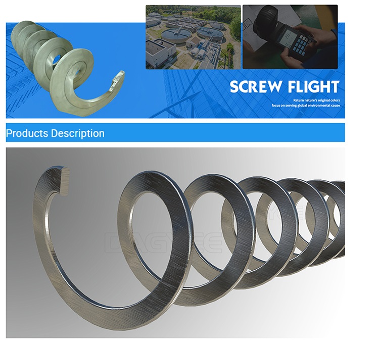
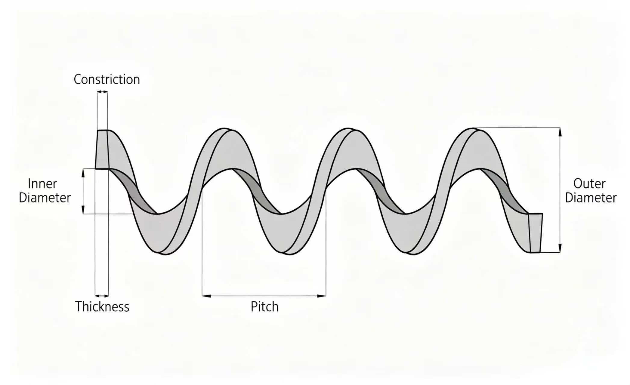
Before diagnosing faults, engineering teams need to recognise the natural operational boundaries built into every screw flight design. Helical blades rely on consistent outer diameter, uniform helical pitch and stable surface integrity to generate forward material thrust. Once geometry or surface condition deviates from original design specifications, conveying performance begins to deteriorate.
Screw flight performance depends on four controllable variables: material abrasiveness, conveyor filling ratio, operating rotation speed and surface corrosion exposure. Sludge mixed with sand, grit and inorganic particulate matter creates continuous three-body abrasion against flight outer edges. High filling levels increase friction load across the full flight surface, while elevated rotational speed amplifies contact frequency between blade surfaces and transported media. In corrosive wastewater environments, chemical attack combines with mechanical wear to accelerate degradation far faster than dry bulk material working conditions.
A common misconception among site operators is that minor visible wear does not require attention. In practice, uniform edge loss reduces effective flight diameter, widens clearance between flight tips and the trough wall and creates circulating material eddies. These eddies further accelerate localised abrasion, creating a self-reinforcing cycle of accelerated component ageing.
Table 1: Screw Flight Material Technical Parameter Specification Table
| Flight Material Grade | Base Hardness (HB) | Typical Working Environment | Abrasion Resistance | Corrosion Resistance | Recommended Maximum Continuous Temperature | Common Application Scenario |
|---|---|---|---|---|---|---|
| Mild Carbon Steel Q235B | 120–160 HB | Dry, non-corrosive low-abrasion bulk solids | Low | Poor | 220°C | Dry grain, general non-abrasive raw materials |
| Wear-Resistance Carbon Steel NM400 | 360–420 HB | High grit, mineral residue, gritty sludge | Excellent | Limited | 240°C | Mining tailings, grit-laden wastewater sludge |
| Stainless Steel SUS304 | 180–220 HB | Fresh wastewater, neutral organic sludge | Moderate | Good (neutral pH) | 300°C | Municipal domestic sludge, food processing waste |
| Stainless Steel SUS316L | 175–215 HB | Weak acid, saline wastewater, chemical sludge | Moderate | Very Good | 320°C | Industrial chemical wastewater, coastal sewage treatment |
| Hardfaced Overlay Flight (Base Carbon Steel + Wear Weld) | Surface > 55 HRC | Severe abrasive sludge with high sand content | Superior | Dependent on base material | 260°C | Dewatered sludge with inorganic grit, long-distance conveying |
Technical Note: Hardfacing only protects flight outer edges. If base metal suffers corrosion, overlay sections may peel off over extended service cycles. Shaftless flight for heavy sludge transport generally avoids plain carbon steel unless protected by additional surface coating.
2. Recognisable Early Warning Signs of Degrading Screw Flight
Catastrophic flight fracture rarely happens without preceding abnormal operating behaviour. Experienced maintenance crews establish baseline operating data during the initial commissioning phase, making subtle deviations much easier to identify during routine rounds. Warning signals fall into four categories: electrical performance changes, acoustic irregularities, throughput instability and visible physical defects.
Stable feed volume paired with slowly rising motor operating current ranks as one of the earliest measurable indicators. As flight geometry degrades, more torque is required to push material forward, and average ampere draw creeps upwards without adjustments to feeding rates or drive speed settings. Operators often dismiss small current rises as normal load fluctuation, but consistent upward trends over multiple weeks signal developing flight wear.
Unusual vibration and periodic noise represent another clear alert. Continuous low-frequency vibration typically points to uneven flight load distribution. Regular rhythmic scraping noise indicates flight tips contacting the inner surface of the conveyor trough. Random sharp impact sounds often signal loose welded flight segments or foreign objects trapped between blade sections.
Fluctuating discharge rates and recurring local blockages also deserve close attention. When flight surfaces build up caked sludge or flight edges wear unevenly, material flow cannot maintain a stable forward pattern. Material slides backward rather than advancing toward the discharge outlet, causing uneven output and frequent blockages near the feed zone or intermediate hanger bearing positions. Operators who repeatedly clear blockages without investigating root mechanical faults will face worsening failure risks over time.
Table 2: Screw Flight Early Warning Signal Identification Checklist (On-Site Daily Inspection)
| Inspection Item | Acceptable Normal Status | Warning Condition (Schedule Detailed Inspection) | Critical Alarm Condition (Plan Shutdown Immediately) |
|---|---|---|---|
| Motor running current | Consistent within ±5% of baseline commissioning value | Sustained rise over 10% baseline reading | Current exceeds motor rated working load |
| Vibration & noise | Smooth running, constant low hum | Intermittent scraping or low-frequency vibration | Persistent metal collision noise, heavy frame vibration |
| Conveying throughput | Stable output matching design capacity | Discharge volume fluctuates >15% under fixed feed rate | Output drops below 60% of rated capacity |
| Blockage frequency | Rare blockages (less than once monthly) | Blockages occur weekly after routine cleaning | Blockages appear within hours after clearing |
| Visual flight condition (via inspection hatches) | Smooth surface, uniform flight thickness | Visible edge thinning, surface caking or minor pitting | Obvious bending, visible cracks or broken flight segments |
| Material backflow | Minimal backward material migration | Regular material accumulation behind flight sections | Significant sludge backflow towards feed hopper |
3. Six Primary Screw Flight Failure Modes, Root Causes & Practical Solutions
3.1 Abrasive Edge Wear – The Most Common Industrial Flight Fault
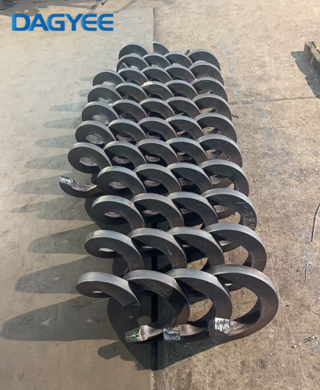
Flight outer edges bear the highest contact pressure against bulk media, so uniform edge abrasion occurs across nearly all screw conveyor installations. Grit, fine rock particles and mineral fragments trapped between flight tips and the trough liner gradually grind away blade thickness.
Operating parameters amplify wear speed. Excessive rotation speed increases particle impact frequency, while poorly controlled high filling ratios create dense material layers that continuously rub against flight surfaces. Carbon steel flight without wear protection will show measurable edge loss within months when transporting gritty wastewater sludge.
Minor uniform wear can be recovered through on-site hardfacing welding on flight peripheries. Once flight thickness reduces by more than one-third of original specification, rebuilding via welding becomes uneconomical, and full flight replacement is recommended. Operators can extend service life by moderately reducing conveyor rotation speed and installing debris screens to limit oversized abrasive foreign material entering the conveyor trough.
3.2 Flight Distortion, Bending and Permanent Helical Deformation
Flight bending almost always originates from overload shock loads. Attempting to restart a fully packed conveyor trough forces extreme torque onto helical blades, twisting flight geometry and distorting the designed helical pitch. Trapped solid debris such as metal fragments, construction rubble and large sludge lumps also create concentrated stress points that permanently deform flight sections.
Slightly distorted flight can undergo professional mechanical calibration, but heavily twisted blades cannot recover consistent pitch and concentricity even after straightening attempts. After correction, residual internal stress leads to accelerated fatigue cracking during continuous operation. The most reliable long-term solution remains full flight replacement once deformation exceeds acceptable tolerance ranges. Facilities should install overload protection relays and enforce lockout-tagout procedures before clearing blockages to avoid forced startup under loaded conditions.
3.3 Flight Root Cracking and Weld Joint Rupture
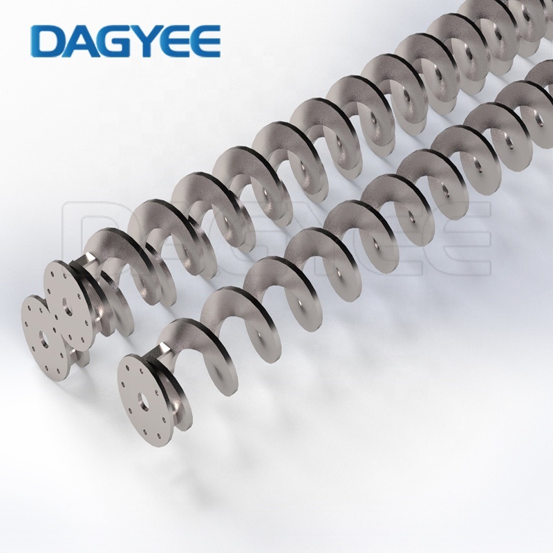
Most custom-manufactured screw flight for large-diameter conveyors uses segmented blade welding at the flight-to-central shaft connection. These welded joints act as natural stress concentration zones under repeated cyclic loading. Incomplete weld penetration during fabrication creates hidden microcracks that expand slowly during daily operation.
Corrosive sludge seeps into tiny weld gaps, corroding metal from within and weakening joint strength further. Misaligned central shafts distribute load unevenly across flight sections, accelerating crack propagation. Early surface cracks can be ground out and fully re-welded with reinforcing gusset plates fitted at flight roots. Large penetrating fractures or separated flight segments present major safety risks; operation must stop immediately to prevent broken flight pieces jamming the conveyor assembly. For new equipment orders, specify one-piece continuous flight for heavy-load sludge conveying applications wherever budget permits.
3.4 Surface Corrosion, Pitting and Local Perforation
This failure mode dominates wastewater and chemical processing environments. Neutral, acidic or saline sludge creates electrochemical corrosion on unprotected steel surfaces. Rough areas caused by minor abrasion act as initiation points for pitting, creating small cavities that expand gradually over time. Corroded rough surfaces also encourage sludge adhesion, compounding flight performance loss.
Light surface rust and shallow pitting can be treated via abrasive blasting followed by anti-corrosion coating. Facilities regularly handling chemically active wastewater should upgrade flight material grade from carbon steel to SUS304 or SUS316L stainless steel. Operators can reduce corrosion rates by fully emptying and cleaning conveyors after operation cycles, avoiding long-term static retention of wet sludge inside the trough.
3.5 Material Caking and Surface Flight Binding
High-moisture organic sludge possesses strong adhesive characteristics. Over time, compressed material layers solidify and stick firmly onto flight surfaces. These hardened deposits shrink the effective flight outer diameter, reduce conveying efficiency and create uneven friction patterns. Many teams attempt to solve frequent blockages by increasing drive power, which only accelerates flight wear and motor overload risks.
Scheduled inspection and mechanical cleaning through access hatches control heavy caking. Polished stainless steel flight or non-stick surface treatments reduce sludge adhesion tendency. Where continuous sticky media transport cannot be avoided, engineers can adjust flight pitch designs and optimise feeding continuity to prevent prolonged static contact between sludge and flight surfaces.
3.6 Flight Rubbing Against Conveyor Trough Liner
Screeching metal contact noise signals flight-to-trough rubbing. Primary triggers include bent main shafts, worn intermediate hanger bearings, inaccurate installation concentricity and long-term thermal expansion deformation. Constant friction wears both flight edges and the trough liner simultaneously, raising overall maintenance expenditure. Technicians must check shaft straightness, replace degraded hanger bearings and restore the design radial clearance between flight outer diameter and the inner trough wall to resolve this fault.
Table 3: Screw Flight Failure Mode, Root Cause and Remedy Comparison Matrix
| Failure Mode | Primary Root Causes | Short-Term Emergency Remedy | Long-Term Preventive Solution |
|---|---|---|---|
| Abrasive Flight Edge Wear | Gritty material, excessive rotation speed, low-hardness flight material | Hardfacing overlay welding on worn edges | Adopt wear-resistant flight grade, optimise conveyor speed and filling ratio |
| Flight Bending & Distortion | Forced startup under blockage, trapped foreign debris, overload torque | Mechanical calibration for slight deformation; replace severely twisted flight | Install feed inlet debris screen, configure electrical overload protection |
| Flight Root Crack & Weld Breakage | Poor welding penetration, cyclic fatigue stress, shaft misalignment | Grind cracks and perform reinforced full penetration re-weld | Specify continuous one-piece flight; ensure precise shaft alignment during installation |
| Corrosion & Surface Pitting | Acidic/saline sludge, residual wet media, unprotected carbon steel | Blast and apply anti-corrosion coating for light corrosion | Upgrade to stainless steel flight; implement post-operation empty cleaning routine |
| Sludge Caking & Flight Binding | High-viscosity wet sludge, low surface smoothness | Periodic manual cleaning through inspection hatches | Select polished flight surfaces, adjust feeding flow to avoid static sludge accumulation |
| Flight Rubbing on Trough Liner | Worn hanger bearings, bent shaft, assembly misalignment | Readjust concentricity, restore design clearance | Schedule regular bearing replacement and shaft straightness testing |
4. Standard Step-by-Step On-Site Fault Diagnosis Process
Structured diagnosis avoids blind disassembly and unnecessary production downtime when flight irregularities appear. Maintenance supervisors should follow this logical sequence during troubleshooting.
First, record baseline operating data including average motor current, vibration intensity and throughput fluctuation range. Comparing live readings against commissioning benchmarks quickly separates normal variation from developing mechanical faults. Next, perform acoustic monitoring to locate the approximate position of abnormal noise inside the conveyor trough. For fully enclosed units without large inspection hatches, industrial endoscopes deliver visual feedback without full equipment disassembly.
If warning signals continue, fully isolate power, implement lockout-tagout safety protocols and completely empty all material from the conveyor. Technicians can then measure actual flight outer diameter, blade thickness and helical pitch, comparing measurements against original engineering drawings. Data collection clarifies whether the fault originates from wear, deformation, crack formation or surface adhesion. After confirming the exact failure category, teams select the most economical solution: local repair, component reinforcement or complete flight assembly replacement.
5. Structured Preventive Maintenance Schedule to Extend Screw Flight Lifespan
Long flight service life relies on layered inspection cycles combining daily rounds, monthly internal checks and annual full overhauls. Many facilities only respond to failures reactively due to poorly defined maintenance timetables.
Weekly & Daily Rounds
Operators monitor noise, vibration and motor current trends during startup and continuous running. All unusual readings must be logged for tracking over multiple weeks. Staff also record blockage frequency and sludge discharge stability to identify slowly worsening flight conditions at an early phase.
Monthly Internal Inspection
Open inspection hatches to visually assess flight surface conditions. Check for sludge caking, surface corrosion and small weld cracks. Measure clearance between flight tips and trough liner and compare against design tolerances. Carry out local cleaning of accumulated material during each access inspection.
Quarterly Maintenance
Thoroughly remove hardened sludge deposits on flight surfaces. Tighten all shaft and flight connecting bolts, and test overload protection devices to guarantee reliable trip action during unexpected overload events.
Annual Major Overhaul
Conduct comprehensive dimensional measurement across all flight sections. Evaluate wear levels to plan future spare part procurement during scheduled plant shutdown windows. Engineering staff should review material matching performance; if flight degradation happens far faster than design expectations, evaluate upgrading flight material grade for the following operating year.
6. Frequently Asked Practical Engineering Questions
Q1: Can moderately worn screw flight remain in continuous service?
Short-term limited operation is possible, yet once protective surface layers wear away, degradation accelerates exponentially. Extended operation risks sudden flight breakage, shaft bending and permanent damage to the expensive conveyor trough liner. Maintenance should be arranged at the earliest available production shutdown window.
Q2: What key differences exist between shafted flight and shaftless flight maintenance standards?
Shaftless screw flight lacks central shaft support, bearing greater bending stress during sludge transportation. Blockage loads create higher risk of permanent flight distortion. Operators must maintain stricter feed control and avoid large foreign material entering the trough to prevent shock overload.
Q3: How to choose flight material specifically for municipal and industrial sludge conveying?
Neutral municipal domestic sludge works well with SUS304 flight. Sites processing acidic industrial wastewater or saline sewage should select SUS316L. Sludge mixed with high sand and grit content requires wear-resistant steel with edge hardfacing treatment to maximise service intervals.
Conclusion
Screw flight functionality directly determines overall screw conveyor uptime across wastewater treatment, waste management and bulk material handling industries. Recognising early warning indicators, accurately categorising failure modes and implementing systematic preventive maintenance drastically reduces unplanned shutdown losses and cuts long-term component replacement expenditure.
Material selection matching transported media characteristics, properly controlled operating parameters and consistent routine inspections form a complete protection framework for helical flight assemblies. When planning new conveyor procurement or flight replacement upgrades, work with professional equipment engineers to confirm flight thickness, pitch, material grade and surface treatment optimised for your unique sludge or bulk solid properties.
If your operation requires custom-engineered screw flight, wear-resistant modification solutions or technical support for shafted and shaftless conveyor maintenance planning, contact our engineering team for tailored design recommendations and spare part consultation.
Name: Ashely Li
Mobile:+8613961861780
Tel:+8613961861780
Whatsapp:8613961861780
Email:info@dagyee.com
Add:Room 302, Building 11-4, Hongyi Road, Xinan Town, Xinwu District, jiangsu Province, China