English
 Chinese
info@dagyee.com
+8613961861780

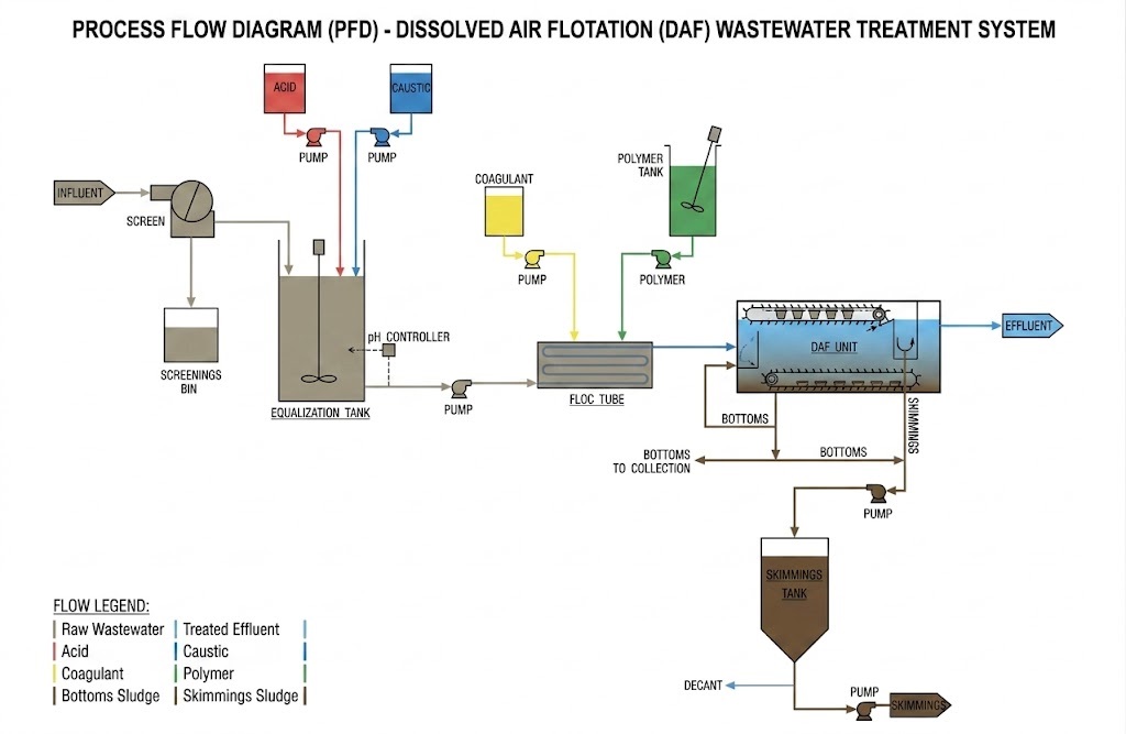
I. Core Principle of DAF Technology: Understanding the Underlying Logic of "Bubble Separation"
Many practitioners using DAF equipment only know that it can remove suspended solids, oils and other impurities from wastewater, but they have little understanding of its core principle, which leads to a passive situation in terms of parameter adjustment and fault handling later. In fact, the working logic of DAF is not complicated. The core lies in achieving efficient separation of pollutants from water through four key steps: "aeration - release - adhesion - separation". The specific process is as follows:
1. Dissolution stage: In this stage, air is fully mixed with water under high pressure, allowing the air to dissolve into the water and form supersaturated dissolved air water. The core of this stage is to ensure the efficiency of air dissolution, laying the foundation for the generation of tiny bubbles in the subsequent process. This is also the fundamental difference between DAF technology and ordinary air flotation technology.
2. Release stage: The supersaturated dissolved gas water is passed through a dedicated release device, which rapidly depressurizes it to atmospheric pressure. At this point, the dissolved air in the water will rapidly precipitate, forming a large number of tiny bubbles. The particle size of these bubbles is typically controlled within the range of 20-100 μm (bubbles of this size have the best ability to adhere to pollutants and can float stably).
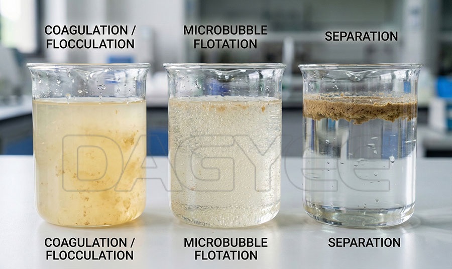
3. Attachment Stage: The tiny bubbles fully come into contact with the suspended matter, colloidal particles, and oil and other pollutants in the wastewater. By virtue of the surface tension of the bubbles, the pollutants are firmly adhered to the surface of the bubbles, forming a "bubble-pollutant" complex. It should be noted that if the pollutant particles in the wastewater are too fine, a coagulant needs to be added in advance to cause the fine particles to aggregate into larger flocs, thereby enhancing the attachment effect.
4. Separation stage: The "bubble-pollutant" complex has a lower density than water and will rapidly rise to the surface under the influence of buoyancy, forming a floating scum layer. The scum is removed by the scraping equipment, while the purified clear water is discharged from the bottom, thus completing the solid-liquid separation process.
In simple terms, the core advantage of DAF technology lies in "microscopic bubbles" - the smaller the bubbles and the more uniform their distribution, the larger the contact area with the pollutants, and the higher the separation efficiency. This is also one of the core directions for optimizing subsequent process parameters.
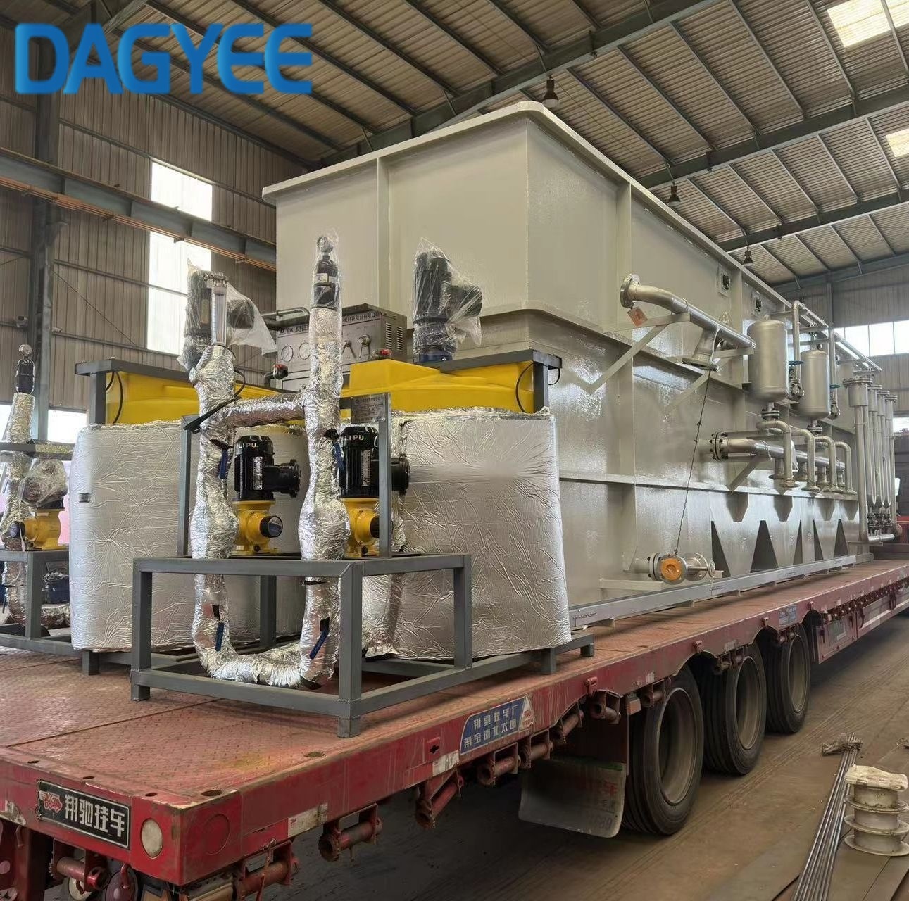
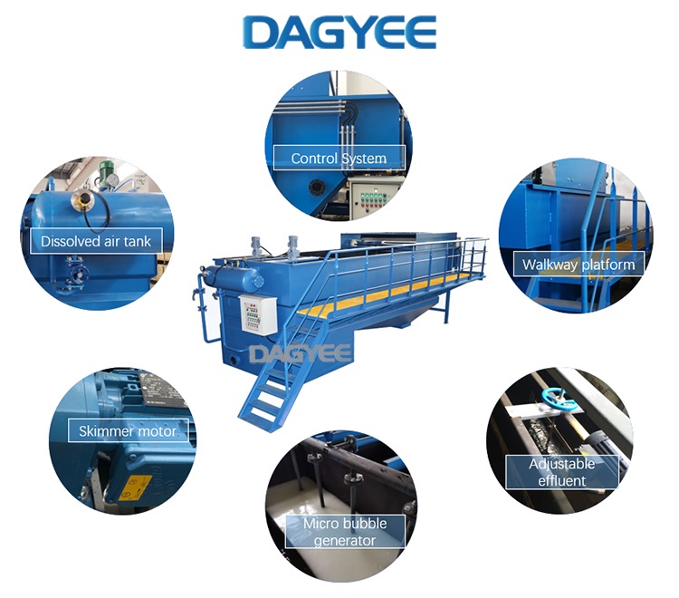
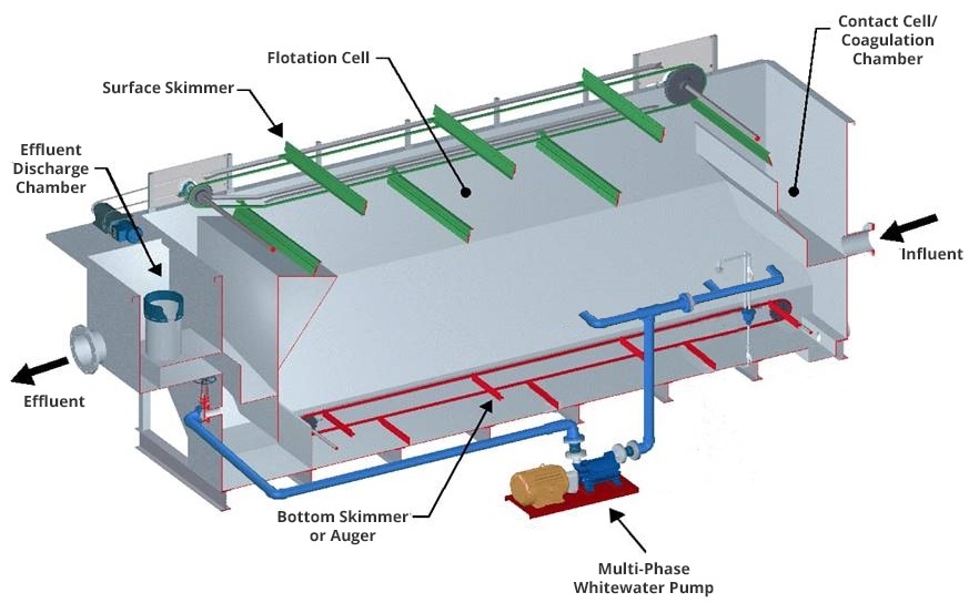
II. Core Components of the DAF System: Four Major Components Determine Processing Effect
1. Gas dissipation system: The "heart" of DAF
The dissolved gas system is the core for generating supersaturated dissolved gas water. It mainly consists of a dissolved gas tank, an air compressor, and a circulating water pump. Its performance directly determines the efficiency of air dissolution and the quality of subsequent bubbles. In the paper, through numerous experiments, it was concluded that the pressure, liquid level, residence time of the dissolved gas tank, and the air supply volume of the air compressor are the key factors affecting the dissolved gas effect.
Design Key Points: The dissolved air tank is recommended to have a vertical structure. The volume should be determined based on the treatment water volume, and the residence time should be controlled within 2 to 5 minutes. The air compressor should be an oil-free type to prevent oil contamination of the water body. The air supply volume should match the circulating water volume. The head of the circulating water pump needs to meet the requirements of the dissolved air pressure. Usually, it should be controlled at 0.3 to 0.5 MPa to ensure that the air can be fully dissolved in the water.
2. Release mechanism: The "generator" of tiny bubbles
The function of the release device is to rapidly and uniformly release the air from the supersaturated dissolved gas water into tiny bubbles. The structural design of this device directly affects the bubble size and the uniformity of distribution. The paper compared the performance of various release devices (needle type, orifice plate type, jet type), and concluded that the jet type release device produces the smallest bubble size (20-50 μm), the most uniform distribution, the best effect in adhering to pollutants, and is less prone to clogging, making it suitable for most engineering scenarios.
Notes: The release device should be cleaned regularly to prevent impurities from blocking the pore size, which could cause the bubble size to increase and the separation efficiency to decrease; During installation, it should be evenly distributed on the bottom of the air flotation tank to ensure that the bubbles can fully contact with the wastewater.
3. Air flotation tank: The "main battlefield" for separation (key to flow field design)
(3) Sludge scraping device: A continuous sludge scraping machine is selected. The scraping speed is controlled at 0.5 - 1 m/min to prevent the sludge from being scraped off too quickly, which could cause the sludge to break and re-enter the water body.
4. Auxiliary System: Ensuring the stable operation of the system
The auxiliary system includes the coagulation dosing system, the sludge discharge system, and the control system. The coagulation dosing system is used to add coagulants such as PAC and PAM to cause fine pollutants to coalesce into flocs, enhancing the adhesion effect of bubbles; the sludge discharge system is used to remove the settled sludge at the bottom of the air flotation tank to prevent sludge accumulation from affecting the flow field; the control system is used to monitor parameters such as dissolved air pressure, water flow velocity, and liquid level, enabling automatic operation and reducing labor costs.
III. Optimization of DAF Process Parameters: Step-by-step guidance to achieve optimal conditions
| Application Scenario | Dissolved Air Pressure (MPa) | Recycle Ratio (%) | Coagulant Dosage (mg/L) | Bubble Size (μm) | Treatment Efficiency (SS Removal %) |
| Water Purification (Low Turbidity) | 0.3-0.4 | 15-20 | 20-50 | 30-60 | ≥90 |
| Municipal Wastewater Treatment (Pretreatment) | 0.4-0.5 | 20-30 | 50-100 | 40-80 | ≥85 |
| Food Industry Wastewater (Oily) | 0.4-0.6 | 25-35 | 80-150 | 20-50 | ≥92 |
| Textile Industry Wastewater (High Color) | 0.35-0.55 | 20-25 | 100-200 | 30-70 | ≥88 |
| Paper Industry Wastewater (Fibrous) | 0.45-0.6 | 30-40 | 120-180 | 20-60 | ≥93 |
Additional Note: The above parameters represent the optimal range based on the foundation. During actual operation, adjustments may be made based on the influent water quality (turbidity, SS content, pollutant types), and the treatment volume. For instance, when the SS content in the influent water is too high, the return ratio and the dosage of coagulant can be appropriately increased; when the oil content in the water is high, the bubble particle size can be reduced to enhance the adhesion effect.
IV. DAF Engineering Application Cases: Practical References for Different Scenarios
Theoretical combination with practice is the core value of the DAF technology. The paper includes multiple DAF engineering cases from different fields, covering water supply, urban sewage, and industrial wastewater. Three typical cases are selected and their design parameters, operation effects, and precautions are detailedly analyzed to provide practical reference for practitioners (keywords: DAF engineering cases, solvothermal air flotation industrial application, DAF wastewater treatment cases):
Case 1: Water Supply Purification Project of a City's Waterworks
Project scale: The treated water volume is 200 m³/d. The raw water is surface water with a turbidity of 20-50 NTU. The main pollutants are algae, plankton and fine silt. The required effluent turbidity is ≤ 1 NTU.
DAF system design: A horizontal-flow air flotation tank is adopted. The volume of the dissolved air tank is 10 m³. The jet-type release device is used. The pump's head for circulation is 0.4 MPa. The return ratio is 20%. The dosage of coagulant is 30 mg/L (PAC).
Operation effect: The effluent turbidity is stable at 0.5 - 0.8 NTU, with a SS removal rate of 92% and an algae removal rate of 95%. It meets the drinking water standards for tap water. The operation energy consumption is 0.35 kWh/m³, the treatment cost is relatively low, and the land area is only one-third of that of the traditional sedimentation tank.
Case 2: Oil-containing wastewater treatment project of a food processing factory
Project scale: The treated water volume is 100 m³/d. The wastewater contains 500-800 mg/L of oil, 1000-1500 mg/L of SS, and 800-1200 mg/L of COD. The effluent is required to have an oil content of ≤ 10 mg/L and a COD concentration of ≤ 100 mg/L.
DAF system design: Utilize a shallow air flotation tank (with optimized flow field design), with a dissolved gas pressure of 0.5 MPa, a reflux ratio of 30%, a dosage of 120 mg/L for the coagulant (PAC + PAM combined addition), and the bubble particle size controlled within 20-50 μm.
Operation effect: The oil content in the effluent is ≤ 8mg/L, the SS removal rate is 94%, the COD removal rate is 75%, fully meeting the industry discharge standards. Through DAF pretreatment, the subsequent biochemical treatment load is reduced by 30%, significantly saving operating costs.
Case 3: Deep Treatment Project for Wastewater from an Ink and Dye Factory
Project scale: The treated water volume is 120 m³/d. After the wastewater undergoes biochemical treatment, the problems of high color and excessive fine suspended solids still exist. The color is 50-80 times higher, and the SS content is 100-150 mg/L. The required effluent color should be ≤ 10 times and SS ≤ 20 mg/L.
DAF system design: A vertical flow aerated tank is adopted. The dissolved air pressure is 0.45 MPa, the return ratio is 25%, the dosage of coagulant is 150 mg/L, and a de-colorizing agent is additionally added. The release device is evenly distributed to optimize the flow field and avoid short-circuiting.
Operation effect: The effluent color is ≤ 8 times the standard, the SS removal rate is 88%. The treated wastewater can be recycled, achieving water resource recovery and utilization. This saves the company approximately 150,000 yuan in water expenses annually.
V. DAF Equipment Selection, Energy Consumption Analysis and Fault Diagnosis
For engineering practitioners, equipment selection, energy consumption control, and fault handling are the key factors ensuring the long-term stable operation of the DAF system. Based on the research results in the paper, a practical guide has been compiled to help everyone avoid selection mistakes, reduce operating costs, and quickly solve faults.
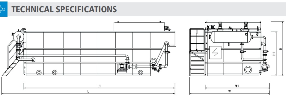
| DAF Model | Qmax (m³/h) | Piping Connections (DN) | Physical Dimensions (m) | ||||||||
| Inlet | Outlet | Sludge | Vent | L | L1 | W | W1 | H | H1 | ||
| DAF-002 | 2 | DN50 | DN50 | DN100 | DN100 | 3.4 | 2.5 | 3.4 | 1.2 | 2.2 | 1.7 |
| DAF-003 | 3 | DN50 | DN50 | DN100 | DN100 | 3.7 | 2.8 | 2.4 | 1.2 | 2.2 | 1.7 |
| DAF-005 | 5 | DN80 | DN80 | DN100 | DN100 | 4.0 | 3.0 | 2.4 | 1.2 | 2.2 | 1.7 |
| DAF-010 | 10 | DN100 | DN100 | DN100 | DN100 | 4.6 | 3.8 | 2.7 | 1.4 | 2.4 | 1.9 |
| DAF-015 | 15 | DN125 | DN100 | DN150 | DN100 | 5.6 | 4.5 | 2.9 | 1.7 | 2.5 | 2.0 |
| DAF-020 | 20 | DN150 | DN150 | DN150 | DN100 | 5.9 | 4.8 | 3.2 | 2.0 | 2.5 | 2.0 |
| DAF-030 | 30 | DN150 | DN150 | DN150 | DN100 | 6.8 | 5.5 | 3.2 | 2.2 | 2.7 | 2.2 |
| DAF-040 | 40 | DN200 | DN150 | DN150 | DN100 | 8.0 | 6.7 | 3.6 | 2.6 | 2.7 | 2.2 |
| DAF-050 | 50 | DN200 | DN150 | DN150 | DN100 | 8.4 | 7.0 | 3.6 | 2.6 | 2.7 | 2.2 |
| DAF-060 | 60 | DN250 | DN200 | DN150 | DN100 | 9.9 | 8.4 | 3.8 | 2.8 | 2.9 | 2.4 |
| DAF-070 | 70 | DN250 | DN200 | DN150 | DN100 | 10.5 | 9.0 | 3.8 | 2.8 | 2.9 | 2.4 |
| DAF-080 | 80 | DN250 | DN250 | DN150 | DN100 | 12.0 | 10.5 | 4.0 | 3.0 | 2.9 | 2.4 |
| DAF-100 | 100 | DN300 | DN250 | DN150 | DN100 | 12.0 | 10.5 | 4.2 | 3.2 | 2.9 | 2.4 |
| DAF-120 | 120 | DN300 | DN250 | DN150 | DN100 | 12.5 | 11.4 | 4.4 | 3.4 | 2.9 | 2.4 |
Misconception 1: Blind pursuit of "large processing capacity" - When selecting equipment, it is sufficient to reserve 10-20% of the actual processing water volume. Excessively large equipment will lead to increased energy consumption and higher investment costs.
Misconception 2: Ignoring water quality compatibility - For oily wastewater, release devices and slag removal devices that can withstand oil contamination should be selected; for highly corrosive wastewater, 304 stainless steel materials should be used to prevent equipment corrosion.
Misconception 3: Focusing solely on equipment price while neglecting after-sales service - DAF equipment requires regular maintenance. When selecting the equipment, it is necessary to choose a manufacturer that has a complete after-sales system and can provide on-site debugging and troubleshooting services.
Selection core principle: Based on the treatment scenario (wastewater supply/ sewage/wastewater from industrial sources), the quality of incoming water, and the treatment volume, determine the tank type, dissolved air system, and release device type. Prioritize the selection of energy-saving equipment (such as oil-free air compressors, efficient dissolved air tanks), while also considering the investment cost and operating cost.
VI. Contact Us for More Information
If you are interested in learning more about our DAF system for your water treatment project, please contact our sales team.
Name: Ashely Li
Mobile:+8613961861780
Tel:+8613961861780
Whatsapp:8613961861780
Email:info@dagyee.com
Add:Room 302, Building 11-4, Hongyi Road, Xinan Town, Xinwu District, jiangsu Province, China